Articles with tag: "flight test"

(Note: figures do not appear in the summaries below)
  1. The Icing Problem

    "Aircraft are now capable of flying in icing clouds without difficulty, however, because research by the NACA and others has provided the engineering basis for icing protection systems"

    "THE ICING PROBLEM - CURRENT STATUS NACA TECHNIQUES AND RESEARCH" 1

    Abstract

    This paper summarizes some of the techniques used in N.A.C.A. research programs, in flight and in tunnels, to solve aircraft icing problems and it indicates the scope of the data available for the design of aircraft icing protection systems. Sufficient data have been obtained, generalized where possible, and techniques have been established whereby icing-protection requirements for most aircraft components can be determined sufficiently accurately for engineering purposes. The Appendices discuss the icing facilities at the N.A.C.A. Lewis laboratory in detail, specific test equipment and techniques used in conducting tests in icing wind tunnels, and several icing instruments.

    Introduction

    This is an excellent summary by Uwe …

    read more
  2. NACA-TN-2212

    "in icing conditions, periodic attempts should be made to throwoff the accretions by increasing propeller speed."

    "The Effect of Ice Formations on Propeller Performance" 1

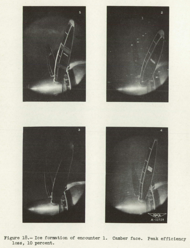
    Figure 18. Ice formation of encounter 1. Camber face. Peak efficiency loss, 10 percent.

    Abstract

    Measurements of propeller efficiency loss due to ice formation are supplemented by an analysis to establish the magnitude of efficiency losses to be anticipated during flight in icing conditions. The measurements were made during flight in natural icing conditions; whereas the analysis consisted of an investIgation of changes in blade-section aerodynamic characteristics caused by ice formation and the resulting propeller efficiency changes. Agreement in the order of magnitude of efficiency losses tobe expected is obtained between measured and analytical results. The results indicate that, in general, efficiency losses can be expected to be less than 10 percent; whereas maximum losses, which will be encountered only rarely, may be as high as 15 or 20 percent. Reported. losses larger than 15 or 20 percent, based …

    read more
  3. NACA-RM-E7H26a

    "The current use of improved airplane ice-prevention equipment has extended operations in icing conditions and thus accentuated the need for protecting aircraft antennas against structural failures resulting from ice accretions"

    "Determination of Aircraft Antenna Loads Produced by Natural Icing Conditions" 1

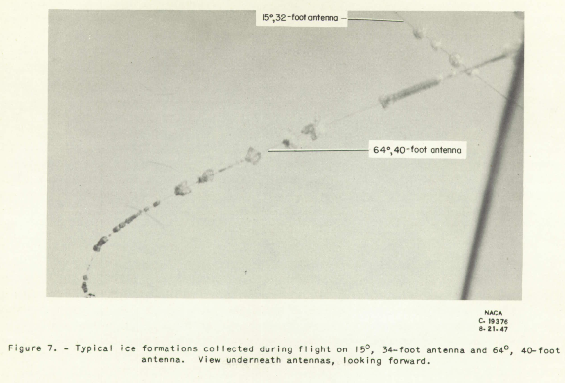
    Figure 7. Typical ice formation collected during flight on 15°, 34-foot antenna and the
64°, 40-foot antenna. View underneath antennas, looking forward.

    Abstract

    A flight investigation was made to determine the effect of distance flown in the icing region, antenna length, and antenna angle on the tension occurring in aircraft antennae while in regions of aircraft icing.

    The, experimental antennas were of lengths ranging from 15 to 43 feet and were placed at angles of 0° to 64° with the airplane thrust axis. Distances up to 256 miles were flown in diverse icing conditions at true airspeeds from 157 to 214 miles per hour and pressure altitudes at which icing conditions were encountered.

    The results indicate that: The effect of ice formation on antenna tension increased with the angle of the …

    read more
  4. Radomes and Antennas

    "The current use of improved airplane ice-prevention equipment has extended operations in icing conditions and thus accentuated the need for protecting aircraft antennas against structural failures resulting from ice accretions"

    Figure 7 of NACA-RM-E7H26a. Typical ice formation collected during flight on 15°, 34-foot antenna and the
64°, 40-foot antenna. View underneath antennas, looking forward.

    These reviews are for studies of the effect of ice on radomes and antennas.

    • Gowan, W. H., Jr.: Vibration and Investigation of CAA Type V-I09 Very-High-Frequency Aircraft Antenna. NACA-RM-SE9D20. 1949.

      "After 7 minutes of icing, however, one antenna element experienced a vibratory failure"
      > review: NACA-RM-SE9D20

    • Kepple, W. L.: Determination of Aircraft Antenna Loads Produced by Natural Icing Conditions. NACA-RM-E7H26a, 1948.

      "The current use of improved airplane ice-prevention equipment has extended operations in icing conditions and thus accentuated the need for protecting aircraft antennas against structural failures resulting from ice accretions"
      > review: NACA-RM-E7H26a

    • Lewis, James P., and Blade, Robert J.: Experimental Investigation of Radome Icing and Icing Protection. NACA-RM-E52J31, 1953.

      "At present very little is known of the effect of radome …

    read more
  5. NACA-RM-E51B12

    "Serious icing of a turbojet-engine installation may render the engine inoperative in a matter of minutes."

    "NACA Investigations of Icing-Protection Systems for Turbojet-Engine Installations" 1

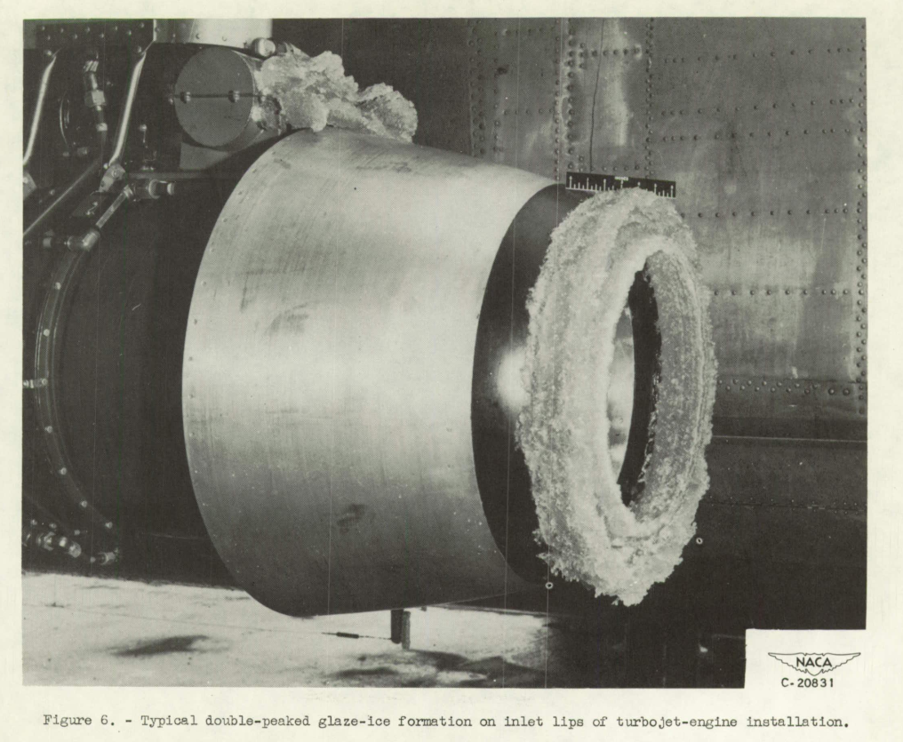
    Figure 6. Typical double-peaked glaze-ice formation on inlet lips of turbojet-engine installation.

    Abstract

    Investigations have been made in flight and in wind tunnels tc determine which components of turbojet installations are most critical in icing conditions, and to evaluate several methods of icing protection. From these studies, the requirements necessary for adequate icing protection and the consequent penalties on engine performance can be estimated.

    Because investigations have indicated that the compressor-inlet screen constitutes the greatest icing hazard and is difficult to protect, complete removal or retraction of the screen upon encountering an icing condition is recommended. In the absence of the screen, the inlet guide vanes of an axial-flow-type turbojet engine constitute the greatest danger to engine operation in an icing condition; a centrifugal- type engine, on the other hand, is relatively unsusceptible to icing once the …

    read more
  6. NACA-RM-E8FO1a

    "The engine was satisfactorily accelerated to take-off power after approximately 45 minutes in the icing condition"

    "Natural Icing of an Axial-Flow Turbojet Engine in Flight for a Single Icing Condition" 1

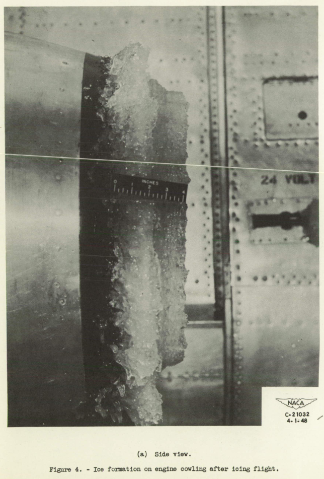
    Figure 4a. Ice formation on engine cowling after icing flight. Side view, the ice is about 4 inch thick in the inlet leading edge.

    Abstract

    An investigation has been conducted In natural icing conditions to determine the effect of ice formations on the performance of an axial-flow turbojet engine. One flight was made in an icing condition in which the liquid.-water content varied from 0.077 to 0.490 gram per cubic meter and the average droplet size varied from 5.4 to 12.1 microns. During a period of 60 minutes in icing, at an engine speed of 11,000 rpm, the tail-pipe temperature increased from 8650 to 9650 F and the jet thrust decreased from 1950 to 1700 pounds. Near the end of the icing period, the engine was satisfactorily accelerated to take-off power.

    Discussion

    As this publication is brief …

    read more
  7. NACA-RM-E8C18

    "Ice formations penetrated to the second-stage rotor blades"

    "Preliminary Results of Natural Icing of an Axial-Flow Turbojet Engine" 1

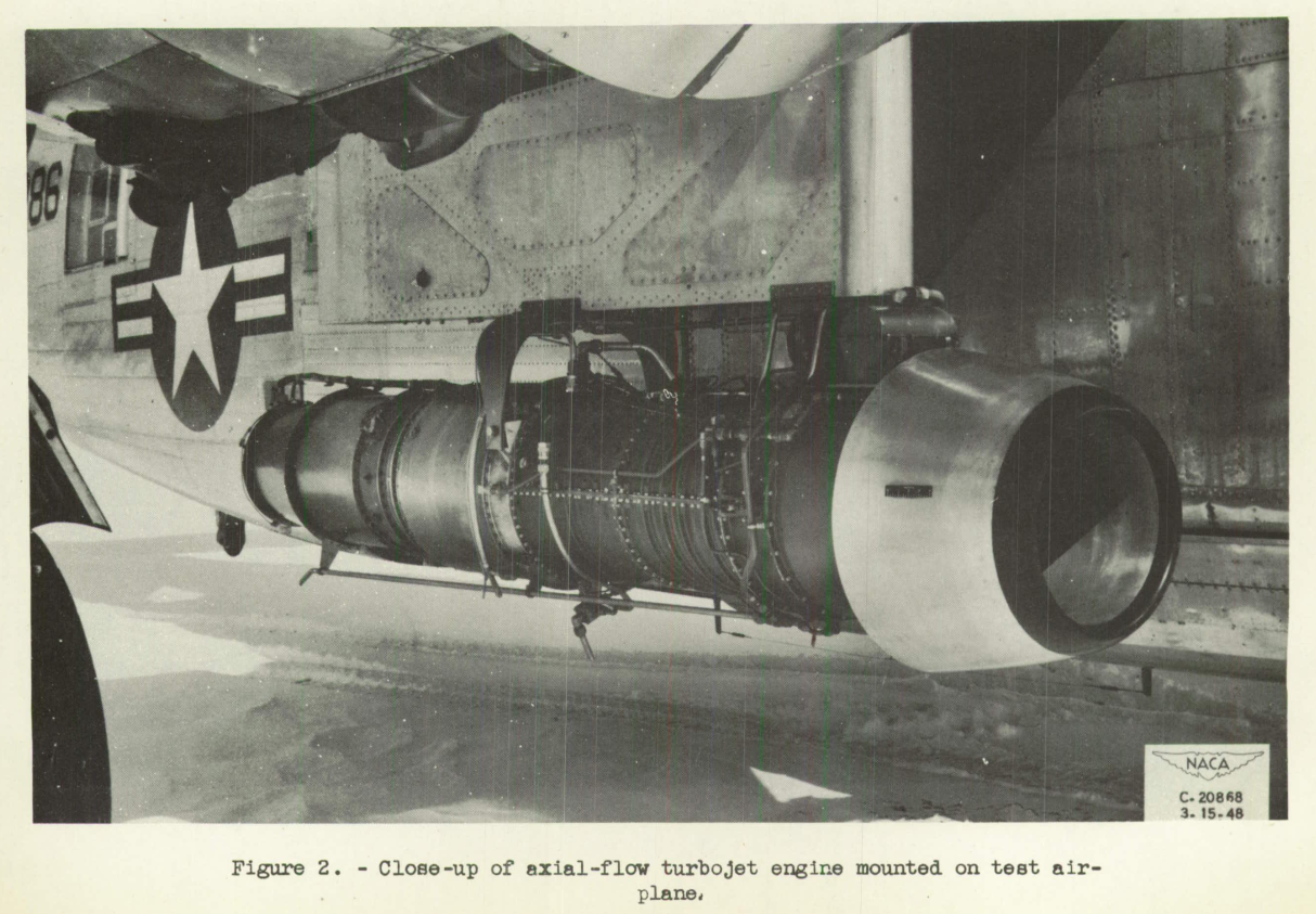
    Figure 2. Close-up of axial-flow turbojet engine mounted on test airplane.

    Abstract

    A flight investigation is being conducted. in natural icing conditions to determine the effect of ice formations on the performance of an axial-flow turbojet engine. One flight was made in icing conditions in which the icing rate varied from 5.1 to 2.1 inches per hour. During a period of 45 minutes in icing, the tail-pipe temperature increased from 761° to 1065° F and the jet thrust decreased from 1234 to 910 pounds. Ice penetrated to the second-stage stator blades. No general conclusions can be reached from these data because the icing condition was relatively light.

    Discussion

    As this publication is brief (18 pages, with 12 of those photos or blank), it is reproduced nearly in its entirety herein.

    The jet engine inlet in this case did not have …

    read more
  8. Engine Inlet Icing

    "The desirability for all-weather operation of turbojet aircraft has necessitated extensive research on methods of icing protection for the various engine components"

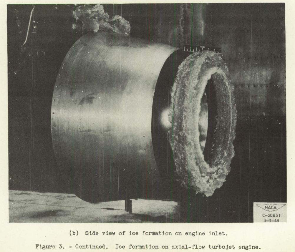
    Figure 3b. Ice formation on axial-flow turbojet engine. Side view of ice formation on engine inlet.
    From NACA-RM-E8C18.

    Discussion

    Publications taken largely from The Historical Selected Bibliography of NACA-NASA Icing Publications, "Turbine-Type Engine and Inlet Icing Studies" section are reviewed here.

    Reviews

    NACA-TN-1246 "Wind-Tunnel Investigation of Icing of an Engine Cooling-Fan Installation"

    • "The icing of the unprotected installation presents a serious operational problem"

    NACA-RM-E8C18 "Preliminary Results of Natural Icing of an Axial-Flow Turbojet Engine"

    • "Ice formations penetrated to the second-stage rotor blades"

    NACA-RM-E8FO1a "Natural Icing of an Axial-Flow Turbojet Engine in Flight for a Single Icing Condition"

    • "The engine was satisfactorily accelerated to take-off power after approximately 45 minutes in the icing condition"

    NACA-TN-2126 "Improvements in Heat Transfer for Anti-Icing of Gas-Heated Airfoils with Internal Fins and Partitions"

    • "Use of the hot-gas method of anti-icing has been restricted ... because of difficulty in controlling the …
    read more
  9. Tools

    Published: Mon 12 February 2024
    Updated: Wed 16 October 2024

    Aircraft designs for flight in icing are improved and proven effective by several tools, including analysis, icing wind tunnel test, and flight test in icing conditions.

    Design handbooks

    Design handbooks have charts and tables that can be used to perform analyses for aircraft icing and ice protection.

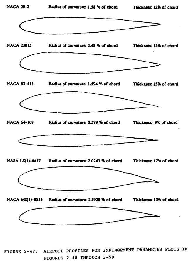
    Figure 2-47. Airfoil profiles for impingement parameter plots in Figures 2-48 through 2-59.
    from "Aircraft Icing Handbook", DOT/FAA/CT-88/8 apps.dtic.mil

    Analysis

    There are computerized icing analysis tools available from NASA, and from commercial vendors. There is also "bespoke" software created for special purposes.

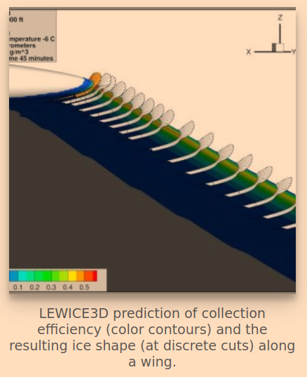
    LEWICE3D. LEWICE3D prediction of collection efficiency (color contours) and the resulting ice shape (at discrete cuts) along a wing.
    from "Glenn Research Center Software" www1.grc.nasa.gov

    Laboratory tests

    A wind tunnel is a large tube with a fan to produce air flow at a calibrated airspeed. Wind tunnels are used to study many effects on aircraft, including icing. Artificially produced ice shapes (often 3D printed) may be adhered to airplane models, and the effects studied.

    To simulate in-flight icing conditions, "Icing Wind Tunnels" often use refrigeration …

    read more
  10. Notes on Flight Testing

    "Tests to determine the performance of an icing protection system ... are of little value ... unless they can be subjected to an analytical treatment, and reduced to a generalised form which is applicable to conditions other than those under which the tests were actually made."

    Lecture No. 12b, "NOTE ON THE FLIGHT TESTING AND ASSESSMENT OF ICING PROTECTION SYSTEMS" 1

    Summary

    An alternative view of how to correlate icing conditions to ice protection performance.

    Key Points

    1. The concepts of protection system "failure" vs. "deficiency" are discussed.
    2. Test conditions specifically planned to find the point of failure or deficiency are recommended.

    Abstract

    Flight tests of an icing protection system consist of functioning tests, tests to determine the internal efficiencies, and tests of the performance in icing. The performance in icing can be determined only if the appropriate measurements are made, and if the flow of protection or the icing severity can be …

    read more
  11. NACA-TN-1598

    "It is significant that the control response of the airplane approached the point of being marginal when all of the airplane except the propeller had accreted ice"

    Figure 13. Formation of ice on horizontal stabilizer. 
Average icing rate, 4 inches per hour; liquid-water content, 
0.4 grams per cubic meter; drop size, 17 microns. (Painted stripes are 
1 in. wide)

    NACA-TN-1598, "Effects of Ice Formations on Airplane Performance in Level Cruising Flight" 1

    Summary

    Airplane levels effects of icing are measured, and broken into major components.

    Key Points

    1. Numerous, excellent quality photos show how icing flight test "should be done".
    2. Airplane levels effects of icing are measured, and broken into major components.
    3. "It is significant that the control response of the airplane approached the point of being marginal when all of the airplane except the propeller had accreted ice."

    Abstract

    A flight investigation in natural icing conditions was conducted by the NACA to determine the effect of ice accretion on airplane performance.

    The maximum loss in propeller efficiency encountered due to ice formation on the propeller blades was 19 percent. During 87 percent …

    read more