"A solution to a problem ... of ice can usually be found, but the solution always involves penalties."
Abstract
Discussion of research on design, development, and flight application of aircraft ice-prevention equipment. Subjects discussed are NACA research on the thermal ice-prevention system, flight investigation of meteorological factors conducive to aircraft icing, calculation of heat required for wing thermal ice-prevention in specified ice conditions, tension in radio antenna wires resulting from ice formation, analytical study of thermal ice-prevention systems applied to light aircraft, effect of ice formations on aircraft performance, etc.
Discussion
This documents the state of the art in 1947 for aircraft ice protection.
Presentations were made on 15 topics.
Here, we will see the abstract of each topic, a summary of results, selected figures, and where to find more information.
CONTENTS
[Links are provided to sections summarized herein.]
LIST OF CONFEREES
TECHNICAL DISCUSSIONS:
REVIEW OF NACA RESEARCH ON THE THERMAL ICE-PREVENTION SYSTEM. By LEWIS A. RODERT, Cleveland, Ohio
TENSION IN RADIO ANTENNA WIRES RESULTING FROM ICE FORMATION. By WILLIAM L. KEPPLE, Cleveland, Ohio
HOT-GAS BLEEDBACK FOR JET-ENGINE ICE PROTECTION. By WILLIAM A. FLEMING, Cleveland, Ohio
ENGINE COOLING FAN AND PROPELLER SPINNER DE-ICING. By E. E. CALLAGHAN, Cleveland, Ohio
PROPELLER ICE PROTECTION BY MEANS OF HOT GASES IN HOLLOW BLADES. By VERNON H. GRAY, Cleveland, Ohio
INTRODUCTION
The conference on Aircraft Ice Prevention was organized by the NACA to convey the Committee's latest research results to those individuals and organizations responsible for the design, development, and flight application of aircraft ice-prevention equipment.
The technical discussions are reproduced herewith in the same form in which they were presented so that distribution might be prompt. The original presentations in this record are considered as complementary to, rather than as substitutes for, the Committee's system of complete and formal reports.
REVIEW OF NACA RESEARCH ON THE THERMAL ICE-PREVENTION SYSTEM. By LEWIS A. RODERT, Cleveland, Ohio
INTRODUCTION
When an unprotected airplane encounters icing conditions, its usefulness is reduced because of the detrimental effects of ice on performance, dependability, and safety. The research of the NACA on ice prevention has been directed to a very large extent toward the use of heat.
A solution to a problem such as that presented by the formation of ice can usually be found, but the solution always involves penalties. In order to judge the relative importance of penalties and benefits connected with thermal ice prevention, it is necessary to understand the severity of the problem when no protection is provided. One phase of the research has therefore been concerned with evaluating the changes in lift and drag of lifting surfaces, loss of thrust, unbalance of propellers, loss of vision through windshields, increased structural loads in external fittings such as radio, antennas, and structural damage due to ice being thrown from propellers or shed from one part and striking another, which occurs when an airplane is flown in icing conditions.
The research on the thermal system was concerned first with discovering heating arrangements for the various vulnerable parts of the airplane. Through these arrangements heat could be delivered to the wings, the windshield, and the propeller. Upon discovery of what appeared to be workable constructional arrangements for heating these parts, the next concern was the quantity and distribution of the heat required.
Inasmuch as the heat required is determined not by the configuration of the vulnerable part alone, but also by the nature of the icing cloud, the research also included a study of meteorological conditions.
The scope of the research has been to determine the detrimental effects of ice, to investigate means for applying heat to the vulnerable parts, to establish design procedures for calculating the heat required, and to determine the cloud characteristics which cause the ice.
In the conduct of the research, useful data has been obtained that is applicable to the range of airplane speed, sizes, and variations in form that exist or are apt to be found in the near future.
Acknowledgment is made to the United Air Lines, Northwest Airlines, and the Air Materiel Command and the pilots of these organizations for their contributions in making possible the extensive flight operations in natural icing conditions.
CONCLUSION The results of NACA research on the thermal ice-prevention system have shown that all entering surfaces of aircraft intended for all-weather operation must be protected and that protection can be provided by the use of heat without significant penalties to the usefulness of the airplane.
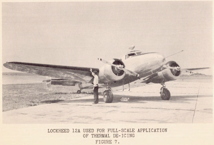
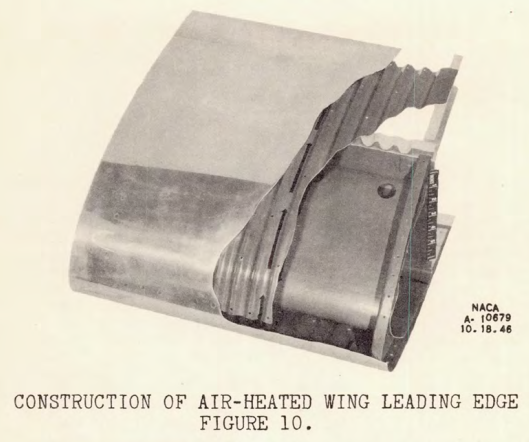
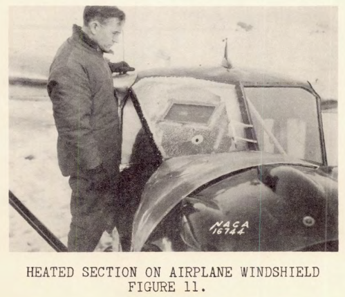
For more information see Ice Protection.
FLIGHT INVESTIGATION OF METEOROLOGICAL FACTORS CONDUCIVE TO AIRCRAFT ICING. By WILLIAM LEWIS, Moffett Field, California
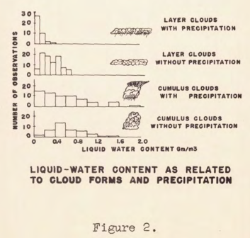
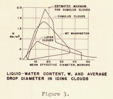
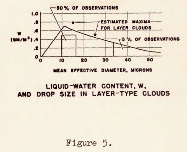
The NACA is currently engaged in a fundamental research investigation of aircraft-icing Problems. The meteorological phase of this investigation consists of the development of instruments required for the evaluation of the critical factors responsible for the formation of ice on aircraft, and the actual measurement of these factors during flight in icing conditions. These measurements furnish data establishing, for the pertinent meteorological variables, the range of values commonly encountered in icing conditions. These data are required as a basis for the definition of the physical characteristics of the maximum icing conditions in which ice-prevention equipment will be expected to provide adequate protection. As a result of this investigation, some progress is also being made toward a solution of some of the problems associated with the forecasting of icing conditions. This paper is directed chiefly to the problem of design conditions, the problems of instrumentation and forecasting are treated only incidentally. In the conduct of this project, a Curtiss-Wright C-46 airplane operated by the Ames Aeronautical Laboratory has been flown in natural icing conditions during the last three winters and a considerable amount of data have been collected. Results of the investigation have been presented in references 1 through 5. During the 1946-17 season, measurements in icing conditions were also made with two airplanes operated by the NACA Flight Propulsion Research Laboratory.
Conclusions
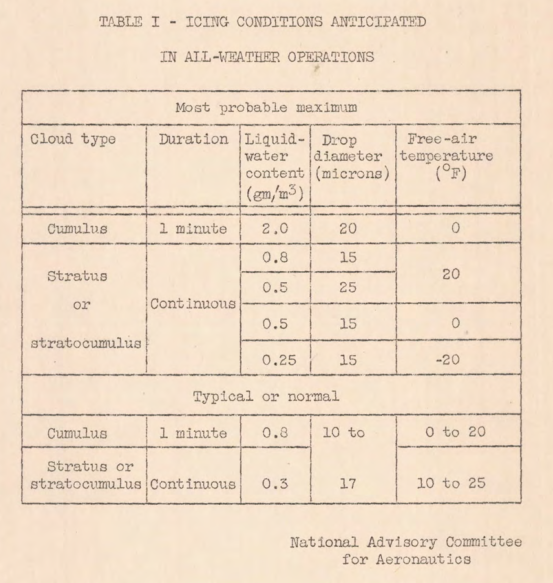
The meteorological conditions conducive to aircraft icing which are considered to be of most interest to the designer of thermal ice-prevention equipment are summarized in table I. The two cases are selected of "most probable maximum" and "typical or normal" icing conditions. The drop-size distribution has not been specified in the table but may be considered uniform for these conditions. In addition to the two conditions specified in the table, however, the designer should give consideration to the possibility of encountering drop sizes larger than 35 microns, although with corresponding low liquid-water content.
As a general conclusion, it is believed that the meteorological factors of icing conditions have been sufficiently defined to allow the design of thermal ice-prevention equipment on a fundamental wet-air basis
For more information see Meteorology of Icing Clouds.
METHOD FOR NUMERICALLY OF WATER IMPINGEMENT CLOUD. By CARR B. NEEL, JR. and NORMAN R. BERGRUN, California
INTRODUCTION
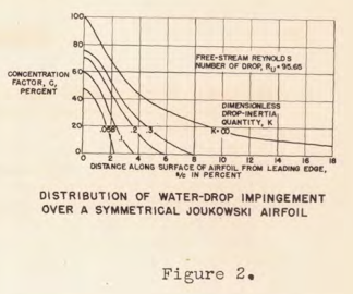
As part of a comprehensive research program directed toward a fundamental understanding of the mechanism of thermal ice prevention for airplanes, the NACA has undertaken an investigation of tha performance of a heated wing or empennage section in specified icing conditions. One of the first essentials of such an investigation is a method for estimating or calculating the area over which water will strike a wing section, and the distribution of water impingement over that area.
Previous investigations of this nature have considered the water-drop trajectories about cylinders (references 1 and 2) and about an airfoil (reference 2). In these studies, the assumption was made that the water drops were sufficiently small to obey Stokes' law of resistance. A more recent investigation on trajectories about cylinders, by Langmuir and Blodgett (reference 3), shows that, for velocities of airplanes and the drop sizes frequently present in clouds, Stokes' law no longer applies and the force acting on the drop can be determined only from a knowledge of the drag coefficient for spheres. Methods of previous investigators were therefore modified to include more accurate values of the drop drag coefficient, and differential equations were established for determining drop trajectories around cylinders, spheres, and ribbons. These equations were placed into forms suitable for use in a differential analyzer and, by utilizing an analyzer, the trajectories were calculated and plotted.
The designer of a heated wing, desiring to know the rate and area of water impingement on the leading edge in a specified icing cloud at a given flight speed, might assume that the impingement will be the same as that for a cylinder with radius equal to the wing leading-edge radius. However, there is some question as to the accuracy of this assumption for large drop diameters and for wing sections with small leading-edge radii. The designer is therefore confronted with the desirability of employing a computation method, preferably without the necessity of a differential analyzer, which will provide some indication of the area and distribution of water impingement on airfoil sections. With this view in mind, the water-drop trajectory equations developed by Langmuir and Blodgett (reference 3) to include the effect of the variable drag coefficient for spheres have been modified to establish a step-by-step integration method applicable to any two-dimensional flow for which the streamline velocity components are known.
The step-by-step integration method permits the calculation of any desired number of water-drop trajectories; although if trajectories for a large range of airspeeds and drop diameters are required, the computation time is large and the desirability of access to a differential analyzer becomes evident. The method also provides a means for estimating the error that will be incurred by replacing the airfoil by a cylinder with a radius equal to the leading-edge radius of the airfoil; and in additional water-impingement data over the entire airfoil surface can be obtained by the integration method.
SUMMARY
A major difficulty in the solution of a trajectory problem in both two-and three-dimensional flow is one of obtaining accurate values of velocity components for streamlines about the body to be investigated. For two-dimensional flow, the analytic determination of the velocity components can be obtained readily for only a few airfoil sections; and for three-dimensional flow, the analytical problem is formidable. Therefore, in order to carry on extensive trajectory computations for families of airfoils and various windshield configurations, considerable research remains in establishing means for experimentally determining air-velocity components. It is believed, however, that the trajectory method that has been presented has merit in the fact that it provides a means for obtaining an indication of the rate and area of water impingement without resorting to a differential analyzer. In addition, the method exceeds the scope of previously available procedures by providing an indication of the distribution of water interception over the area of impingement.
(Editor's note: A complete discussion of the numerical method for calculating trajectories will be found in reference 4.)
Reference 4 was published as NACA-TN-1397, reviewed in Airfoil impingement drop distribution.
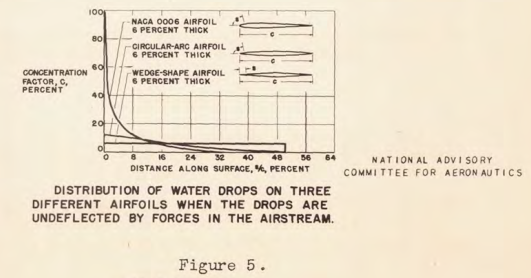
For more information see Water Drop Impingement on Surfaces.
CALCULATION OF HEAT REQUIRED FOR WING THERMAL ICE PREVENTION IN SPECIFIED ICING CONDITIONS. By CARR B. NEEL, JR. and NORMAN R. BERGRUN, Moffett Field, California
INTRODUCTION
The efficient design of wing thermal ice-prevention equipment has been hampered greatly by lack of knowledge of the physical characteristics of the icing conditions upon which to base the design and the exact process by which water intercepted by a heated wing is dispersed.
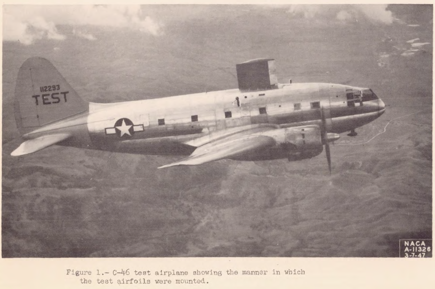
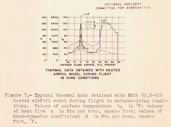
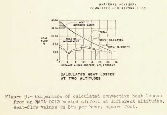
The National Advisory Committee for Aeronautics at present is engaged in an investigation of the meteorological factors conducive to icing and a fundamental study of the heat-transfer :processes which govern the operation of wing thermal ice-prevention equipment. During the winters of 1945-46 and 1946-47 a Curtiss-Wright C-46 airplane which had been provided with a thermal ice-prevention system (reference 1) was equipped with special meteorological and electrically heated test apparatus and flown in natural icing conditions along airline routes over most of the United States. The meteorological data recorded during the icing conditions encountered in the two seasons are presented and discussed in references 2 and 3. The material of this paper was taken from reference 4, and presents an analysis of tbe data obtained during the 1945-46 and 1946-47 winter seasons with two electrically heated test airfoils. The data were analyzed usine heat-transfer equations developed by Hardy of the Royal Aircraft Establishment, Farnborough, England (references 5 and 6). A discussion of the area and rate of water impingement on one of the airfoil sections based. on an analytical study of water-drop trajectories (reference 7) is also presented.
...
From the foregoing discussion, it appears that the extent of knowledge of the meteorology of icing, the impingement of water drops on airfoil surfaces, and the processes of heat transfer and evaporation from a wetted airfoil surface bas been increased to a point where the design of heated wings on a fundamental, wet-air basis now can be undertaken with reasonable certainty.
For more information see Icing Thermodynamics and Ice Protection.
TENSION IN RADIO ANTENNA WIRES RESULTING FROM ICE FORMATION. By WILLIAM L. KEPPLE, Cleveland, Ohio
INTRODUCTION
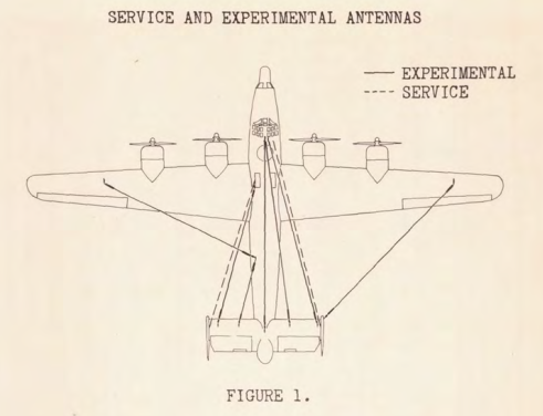
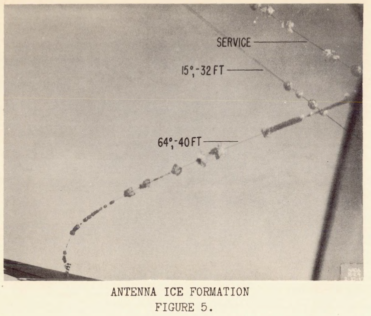
Tbe collection of ice on aircraft radio antennas necessitates an investigation to determine (1) the effect of ice formations on the electrical properties of the antenna, (2) the effect of ice formations on the tension occurring in the antenna, and (3) the decrease in aircraft performance due to antenna ice formations. Information is also needed concerning tbe prevention and removal of ice on radio antennas and tbo installation of the radio antennas in the wings or fuselage.
A flight investigation was conducted at tbe NACA Cleveland laboratory during tho winter of 1946-47 to determine tbe tension occurring in aircraft antennas while flying in natural icing conditions. This investigation was conducted at true airspeeds from 155 to 215 miles per hour and at altitudes at which icing conditions occurred. The effect of the following factors upon antenna tension were investigated : (1) distance flown in the icing region; (2) included angle between the antenna and tbe thrust axis of the airplane; (3) antenna length; and (4) meteorological variables pertinent to ice accretion.
...
Insufficient data were obtained during the investigation to establish a correlation between antenna tension and the meteorological variables. The meteorological only moderate intensity recorded while in these could be encountered in conditions encountered produced icing of and consequently tho antenna tension icing regions would not be as great as high-intensity icing regions.
For more information see Radomes and Antennas.
ANALYTIC STUDY OF THERMAL ICE-PREVENTION SYSTEMS APPLIED TO LIGHT AIRCRAFT. By JAMES G. THOMPSON, Cleveland, Ohio
INTRODUCTION
The thermal ice-prevention system has been adopted for use on commercial transports and large military aircraft and consideration is now given to its practicability on smaller aircraft having a smaller useful load and greater need for economy and simplicity than the larger aircraft. Conveniences and equipment that have long been in use on larger aircraft are today being incorporated in small privately operated aircraft which heretofore were without such advantages. It is therefore anticipated that a serious effort will be made to provide ice protection for small aircraft in the future.
An analytical study was made to determine the thermal requirements of ice-prevention systems for application on three small aircraft with dimensions and specifications covering the range of sizes commonly found in private operation as follows: wing areas of 140, 184, and 250 square feet; sea-level horsepower ratings of 75, 185, and 450 brake horsepower; and cruising speeds of 105, 150, and 205 miles per hour, respectively.
The quantity of heat required for ice prevention on small aircraft has been determined in order that operators may evaluate the penalties in weight, cost, and complications, which must be compensated by the advantages derived from the application of a thermal ice-prevention system. Future industrial progress and research will probably reduce these penalties.
...
A thermal ice-prevention system designed by wet-air method and values of important parameters assumed in this text will probably provide protection in the most adverse conditions that may be encountered in flight; however, it may not be practical to give all types of airplane this maximum protection. Therefore, with the proper selection of the meteorological variables and the degree of protection desired, which are dictated by the airplane's operating schedule, the total amount of heat required can be significantly reduced. By intermittently heating the components, that is, cycling, the amount of heat that must be supplied at any time can be greatly reduced, thus reducing the large quantities of heat required for protecting all of the components simultaneously. By limiting the operations to conditions of lesser severity than those for which larger scheduled aircraft must be designed and by taking advantage of savings that may accrue from intermittently heating the various components, it appears that the thermal ice-prevention system may find practical application on small non-scheduled aircraft.
[No figures were included.]
For more information see Icing Thermodynamics and Ice Protection.
CALCULATION OF HEAT REQUIRED FOR WINDSHIELD THERMAL ICE PREVENTION IN SPECIFIED ICING CONDITIONS. By GEORGE H. HOLDAWAY, Moffett Field, California
INTRODUCTION
One part of a broad icing research program conducted by the NACA has been concerned with the investigation of thermal means of windshield ice prevention. The first satisfactory windshield heating system investigated was the double-panel heated-air type of system tested on a Lockheed 12-A airplane, and described by Rodert and others in reference 1.The tests of reference 1 resulted in the tentative specification of a heat-flow requirement of 1000 Btu per hour per square foot through the windshield outer surface, This value was based on data obtained for a flat-pane, V-type windshield at flight speeds up to 150 miles per hour, and applied to internally heated windshields.
Although this initial research provided some information on windshield heat requirements, the results wore empirical in nature and could not serve as a fundamental basis for the prediction of the internal heating requirements for windshield configurations and flight conditions different than those investigated. Accordingly, a fundamental investigation was undertaken to establish equations for calculating the heat dissipation from the surface of an internally heated windshield in conditions of icing. By measuring the heat flow from various test windshield surfaces during measured icing conditions and comparing these flows with calculated values, the validity of proposed design equations was investigated and design procedures suitable for the prediction of general windshield heating requirements were established.
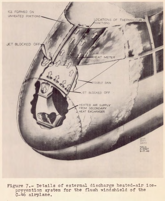
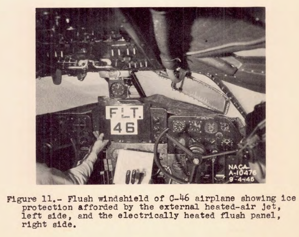
In addition to the research directed towards the establishment of the heat requirement in the case where the heating was supplied internally, a secondary investigation conducted at the same time was concerned with the practicability of ice prevention by the means of discharging a jet of heated air into the windshield boundary layer. This device was initially installed in the C-46 airplane (reference 2) as a means of augmenting the internal, double-panel windshield system. The test results with this initial installation were sufficiently promising to warrant further investigation.
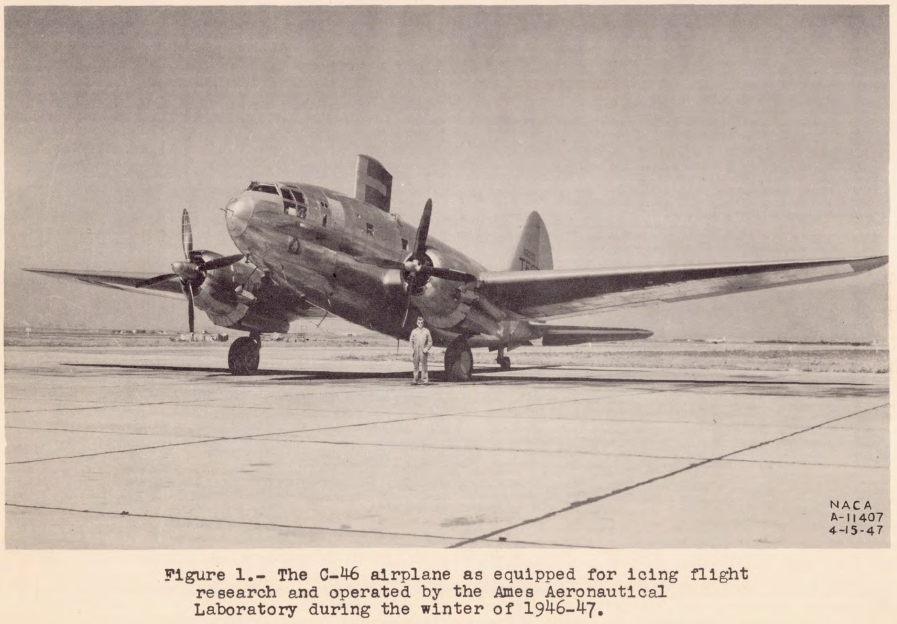
The windshield flight investigations conducted by the NACA Ames Aeronautical Laboratory at Moffett Field, California, during the winters of 1945-46 and 1946-47 were made in clear air and in natural icing conditions with a twin-engine, C-46 cargo airplane, (See fig. 1.) A detailed report of the windshield data obtained its analysis, and a method for calculating the heat required for windshield thermal ice prevention are presented in reference 3.
Additional windshields were tested on a four-engine, B-24 bomber-type airplane operated by the NACA Flight Propulsion Research Laboratory at Cleveland, Ohio, during the winter of 1946-47, (See fig. 2.) The detailed results of this latter investigation are presented in reference 4 by Kleinknecht.
CONCLUSIONS
The following conclusions are based on the analytical studies and test data of this research and should be applicable to windshield configurations and icing conditions similar to those investigated:
1. The coefficient of convective heat transfer for the external surface of flat-plate; V-type, or flush windshield.s can be approximated with an accuracy suitable for design purposes by the use of the established equations for turbulent flow on a flat plate.
2. The heat requirement for ice prevention on a flush or flat-plate airplane windshield during flight in specified icing conditions can be calculated to an accuracy of 20 percent.
3. The complete and continuous prevention of ice accretions on the surface of a flat-plate or V-type airplane windshield, for flight in moderate cumulus icing conditions at speeds up to 300 miles per hour, will require a heat flow from the surface of from 2000 to 2500 Btu per hour per square foot of surface. In the case of continuous flight for the same speed range, in moderate stratus conditions, a heat flow of 1000 Btu per hour per square foot should prove adequate.
4. The complete and continuous prevention of ice accretions on the surface of a flush-type airplane windshield located well aft of the fuselage stagnation region, for a speed range up to 300 miles per hour in stratus and moderate cumulus conditions, can be obtained with a heat flow of 1000 Btu per hour per suuare foot of surface.
5. The tendency of ice to accrete on windshields that are installed flush with the fuselage contours is considerably less than for V-type windshields.
6. The external-discharge system of windshield thermal ice prevention is thermally inefficient and requires a heat supply ap:proximately 20 times that required for an internal system having the same performance.
7 . Windshield installations that conform to the fuselage contours are more adaptable to the use of the external-discharge system than V-type installations, because the heated jet will flow naturally over the windshield surface.
For more information see Windshield Ice Protection.
SUMMARY OF INDUCTION-SYSTEM ICE-PROTECTION REQUIREMENTS FOR RECIPROCATING-ENGINE POWER PLANTS. By WILLSON R. HUNTER, Cleveland, Ohio
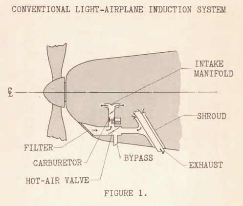
The purpose of this paper is to summarize NACA research in the field of induction-system icing and to review recommendations that should result in inherently ice-free induction systems.
The formation of ice in engine air-intake systems has been a recognized hazard since 1921 when ice was rated as a predominant cause of power failure resulting in airplane crashes. Induction system icing has remained a serious hazard despite the development of relatively ice-free carburetors and despite rigid civil and military regulations requiring alternate or heated-air intakes and alcohol sprays for emergency de-icing. The Civil Aeronautics Administration report of 195 accidents in 1945 involving personal aircraft clearly emphasizes the need for aggressive action in the elimination of this hazard. In 1940, as operations through inclement weather began to increase, the Air Transport Association recognized the need for a better understanding of the causes, effects, and prevention of induction-system icing and requested the NACA to study the problem.
Research was started in 1941 under the direction of a special NACA subcommittee in the Altitude Engine Testing laboratory of the National Bureau of Standards. In 1943 the work was transferred to newly completed research facilities at the NACA Cleveland laboratory with a more comprehensive program under Army sponsorship. The NACA research program included laboratory determination of icing characteristics and de-icing requirements for representative carburetor-supercharger combinations, dynamometer measurements of the effects of ice on engine operation, icing-research-tunnel studies of several Protected air-intake scoops, altitude air-box experiments with alcohol de-icing systems, and flight research under natural and simulated icing conditions, The detection of ice by means of special ice-warning instruments was investigated and a study was made of methods for eliminating the icing problem by suitable design of the air entrance, the throttles, and the fuel-injection device.
Research is now in progress to determine the icing characteristics of light-airplane induction systems in order to determine the criterions for an inherently ice-free system.
Appreciation is extended to the participating airlines, manufacturers, and government agencies for the excellent cooperation and material support throughout this research program.
...
CONCLUSIONS
In summarizing the results of NACA research, the following generalizations can be stated with respect to the icing characteristics of existing systems, the remedial action required to protect these systems, cautions to be observed, and desirable fundamental improvements that can be made in new designs and perhaps retroactively.
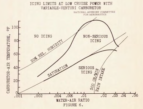
1. The icing characteristics of conventional carburetors of both the suction and pressure type which fuel injected near the throttles present a serious icing hazard in clear air at inlet-air temperatures as high as 70° F.
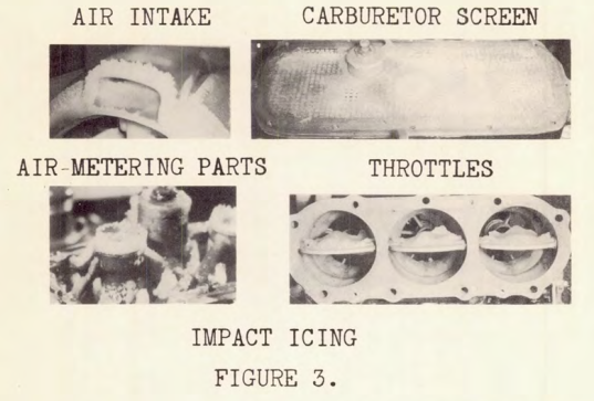
2. Fuel-air ratio and mixture distribution ere adversely affected by icing and by the trapping of water in the air-metering passages of the carburetor and can cause rough running and engine stoppage.
3. Throttles may freeze at a given power setting or when an automatic pressure regulator compensates for the effects of icing and may lead to forced landings with no control over power setting.
4. Hot-air valves may also freeze in the full-cold or full-hot position.
5. Throttles and hot-air selector valves should be of sturdy design and with low control forces to permit mechanically breaking them free when frozen with ice.
6. Duct inlet, carburetor and engine configuration, water injection, power setting, and fuel volatility significantly affected the icing characteristics, but engine size, fuel temperature, fuel-air ratio, and water-alcohol injection did not.
7. Screens and air filters in tne main air duct without bypass constitute an unwarranted icing hazard and should be removed where possible.
8. Exposed fuel nozzles in severe-icing regions may cause leaning out in some pressure carburetors and excessive enrichment in suction carburetors.
9. Remedial ice protection may be provided by means of selecting an alternate air intake by warming the surfaces by applying hot air or alcohol, and by changing the power settings; however, none of these methods fully removes ice formations that occur upstream of the point of protection.
10. A wet-bulb temperature of 60° F affords prompt de-icing of serious-ice formation below the carburetor but may cause icing if applied in dry snow or sleet conditions, and may dislodge sheets of ice that will fall onto the carburetor and disturb operation. Hot-air should be applied when icing begins.
11. Excessive temperatures should be avoided in the hot-air de-icing system to avoid detonation, overcompensation of the fuel-air mixture, and excessive loss of power.
13. The speed-density metering system with oil-heated throttle assembly automatically eliminates throttling icing and. water fouling of the metering system.
14. Spinner fuel injection, manifold injection, or cylinder injection have satisfactorily eliminated fuel-evaporation icing.
15. Inherent ice elimination from the entire induction system may be provided by excluding water from the system, by locating well-designed throttles in warm locations, by making the induction system aerodynamically clean, by injecting fuel where the metal temperatures will remain above freezing, and by adopting a fuel-metering system that does not rely on exposed air-metering passages in potential icing regions.It may therefore safely be concluded that a suitable combination of known induction-system components can now achieve the goal of an efficient and ice-free induction system for all-weather aircraft that will not require pilot control of heating nor need alcohol for emergency de-icing.
For more information see Carburetor and Induction Systems.
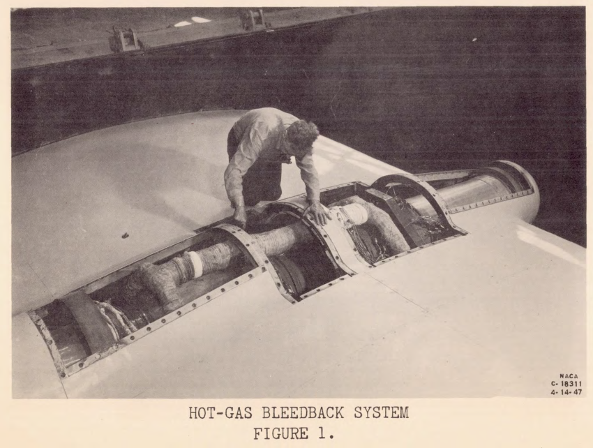
HOT-GAS BLEEDBACK FOR JET-ENGINE ICE PROTECTION. By WILLIAM A. FLEMING, Cleveland, Ohio
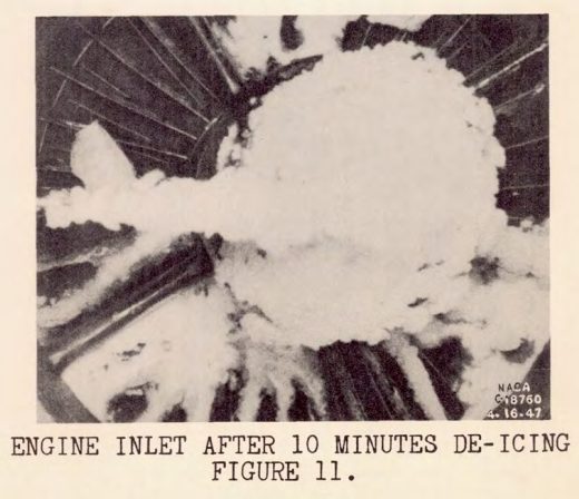
Ice formation on the inlet of a turbojet engine in flight will result in a reduction in thrust and, if icing becomes serious, will render the engine inoperative as a result of high tail-pipe temperatures. Such conditions, particularly with axial-flow compressor engines, make light in icing weather extremely hazardous without some type of equipment to protect the inlet of the engine from icing.
As part of a general program now being conducted st the Flight Propulsion Research Laboratory on ice prevention at the inlet of turbojet engines, an investigation has been conducted in the altitude wind tunnel on a 24C engine to study one phase of the ice-prevention work, The method of ice prevention studied consists of bleeding hot gas from the turbine inlet and injecting it into the air stream ahead of the compressor inlet in order to heat the air above the freezing temperature. This investigation was conducted at altitudes of 5000 and 20,000 feet with ambient-air temperatures from 0° to 35° F and over a range of engine speeds.
The turbine inlet was chosen as the station from which to bleed the gas, because at this station in the engine the gas is at the highest temperature and pressure. Because the temperature of the gas is high, a smaller amount is needed to heat the inlet air above the freezing temperature than would be required if the gas were bled from some other station in the engine. Inasmuch as the pressure at this station is also high, bleeding from the turbine inlet makes it possible to discharge the gas into tho air stream at sonic velocity, thus affording better penetration of the hot air into the cold air.
...
CONCLUSIONS
Ice forms rapidly at the compressor inlet under sevLre icing conditions and is extremely dangerous, inasmuch as the engine may be rendered inoperative within 1 or 2 minutes after icing begins. The hot-gas bleedback system should be used to prevent ice formation at the engine inlet. With configuration 1 or 2, 15 to 30 minutes were required to de-ice the engine inlet with the water spray turned off and once ice had formed, the system was not adequate to de-ice the inlet with the water spray remaining on. With 4 percent of the gas being bled to the engine inlet, the net thrust was reduced 18.8 percent at an engine speed of 12,000 rpm. Raising the inlet air temperature accounts for approximately three-fourths of this decrease in thrust. At similar operating conditions, the specific fuel consumption based on net thrust was increased 16-1/2 percent.
For more information see Engine Inlet Icing.
PROTECTION OF JET-ENGINE INLETS BY MEANS OF INERTIA SEPARATION OF FREE-WATER PARTICLES. By UWE H. VON GLAHN, Cleveland, Ohio
In endeavoring to protect turbojet engines from impact icing, it would appear that the following methods may provide the solution of the icing problem:
1. Bleedback of hot gases from some point in the engine and injecting the gases into the alr stream ahead of the compressor inlet, thue raising the air and water-droplet temperatures above 32° F.
2. Heating all the surfaces subject to icing above 32° F.
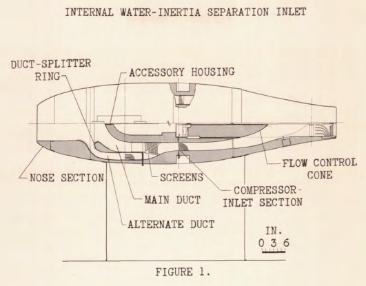
3. Water-inertia separation from the air stream inside the nacelle by suitable inlet design.
4. External water exclusion by suitable inlet design.After a study of the four methods which might be utilized to reduce the icing hazard to a minimum, the conclusion is that no one system can be applied to all aircraft. The methods presented can be applied only at the expense of aerodynamic performance, air frame weight, compressor design, or cabin pressurization.
This paper presents methods 3 and 4 for the ice protection of turbojet engines.
The design criterions for the turbojet engine inlet must include the following:
1. The rate of free-water ingestion must be reduced to a minimum,
2. Ram-pressure recovery must be maintained as high as possible in order not to reduce the engine performance.
3. The Inlet shall be automatic in its operation throughout an icing condition.With these conditions in mind, aerodynamic and preliminary icing tests were conducted in the NACA Cleveland icing research tunnel on experimental nonicing inlets for use with axial-flow turbojet engines.
...
CONCLUSIONS
The results of the investigation of several types of nonicing inlet designs can be summarized as follows:
1. An internal water-inertia separation inlet composed of two concentric ducts can be designed to prevent the entry of most of the free droplets into the outer annular duct. The degree of water separation depends on the ram-pressure recovery that can be tolerated in an icing condition; the better the droplet separation characteristics, the lower the ram-pressure recovery. For normal flight operation, ram-pressure recovery values comparable to those obtained with direct-ram inlets can be obtained. The nacelle-nose inlet, duct-splitter ring leading edge, and alternate-duct elbow surfaces must be heated locally.
2. The single-duct inertia-separation inlets did not show improved performance characteristics over those of the two duct system for an icing condition and also had a low ram recovery for all flight conditions.
3. The annular submerged-nose inlets investigated excluded some of the droplets but were still subject to considerable screen icing. These inlets also exhibited undesirable aerodynamic characteristics.
For more information see Engine Inlet Icing.
ENGINE COOLING FAN AND PROPELLER SPINNER DE-ICING. By E. E. CALLAGHAN, Cleveland, Ohio
In certain installations of high-powered redial engines in airplanes of large gross weights the problem of engine cooling is very difficult.
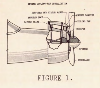
The use of an engine cooling fan, in either the submerged or nacelle type installation, has become the customary means of providing the additional cooling air that is necessary. Any blockage of the fan that would reduce the amount of cooling air must, of course, be prevented and anti-icing or de-icing of the fan is a problem of fundamental importance. Because of this expected loss in cooling air flow due to icing of the fan blades, an investigation of a typical cooling-fan installation was conducted in the icing research tunnel of the NACA Cleveland laboratory to determine the icing characteristics of the fan assembly components, to evaluate the effect of icing on fan performance, and to investigate the effectiveness of several systems of ice protection (reference 1).
CONCLUSIONS
The results of an icing investigation of a conventional radial-engine cooling-fan installation in the icing research tunnel indicate that:
1. The icing of the unprotected installation presents a serious operational problem, Reduction in air flow below the minimum value required for adequate engine cooling occurred within 2 minutes and complete stoppage of the cooling air flow through the fan assembly occurred within 5 minutes under normal icing conditions.
2. Alcohol de-icing of the fan proved to be ineffective and in some cases increased the icing problem by causing large ice formations on the stator vanes.
3. Electrical heat de-icing was the most promising method of de-icing the blades. The fan blades required a minimum power density of 6 watts per square inch but for the stator vanes this power density proved insufficient.
4. The spinner results show that good agreement between the analytical and experimental results are obtainable under known icing conditions.
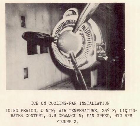
For more information see Engine Inlet Icing.
EFFECT OF ICE FORMATIONS ON AIRPLANE PERFORMANCE. By G. MERRITT PRESTON and. W. V. GOUGH, JR., Cleveland, Ohio
A flight investigation has been conducted in natural icing conditions by the NACA to determine the effect of ice formations on airplane performance.
The lack of quantitative evidence of the serious effect of ice formations on the aerodynamic performance of the propellers has tended to retard the adoption of new and improved systems of propeller ice protection. Numerous pilots have reported serious reduction in airplane performance attributed to inadequate propeller protection. The evidence was inconclusive inasmuch as the effect of ice on the remainder of the airplane and the accuracy of airspeed indication could not be evaluated.
Wind-tunnel tests employing simulated ice formations (reference 1) gave results that indicated a loss in propeller efficiency of 3 percent for level flight. Propeller-whirl tests, during which icing conditions were artificially created, indicated negligible losses (reference 2). Preliminary flight tests (reference 3) indicate a significant loss in performance of the propellers.
The results reported in references 1 and 2 are inconclusive inasmuch as the quantities of ice simulated or obtained are smaller than formations frequently observed during flight in natural icing conditions.
The results reported in reference 3 are also inconclusive inasmuch as they do not permit distinction between the effects of propeller ice and the effects of other ice formations on the performance of the airplane.
Formations of ice on propellers, in addition to deleteriously affecting the propeller performance, has been observed to cause serious unbalance. Also, the natural shedding of ice from the propeller commonly results in fuselage damage and passenger discomfort.
The present investigation was undertaken to determine the effect of ice formation on unprotected propellers by operating in natural icing conditions; by measuring the effects of the ice on the propellers independently of the effects of ice on other parts of the airplane; and, conversely, to measure the effects of ice on other components independently of the effect of ice formations on the propellers. The degree of propeller unbalance that was experienced during flight with ice accretions on the blades was evaluated in the investigation, Photographs were taken in flight of natural ice formations on the airs plane components to permit simulation for aerodynamic studies in wind tunnels.
...
Those data are interpreted in torms of parasite drag by the method given in reference 4. Figure 15 shows the percent drag increase based on tho drag of the ice-free airplane. Ice on the inboard-wing panels accounted for an 8-percent drag increase; tail surfaces, 11-percent drag increase; and, tho outboard-wing panels, 27-percent drag increase, ice on the engine cowlings added 10 percent and the miscellaneous components, the second largest offender, were responsible for 25 percent of tho airplane-drag increase.
This investigation did not include tho determination of such factors as stalling speed, minimum single-engine speed, and low-speed flying qualities. It ie significant to report that the control response of the airplane approached the point of being marginal when the entire airplane, except tho propellers, was iced.
The data and results presented here are directly applicable only to the airplane type used in this investigation nnd under meteorologically similar conditions. However, by proper consideration of such factors as leading-edge radius, loading-edge lengths, and surface areas, the drag data can be used for estimating the effect of ice on tho performance of other airplanes.
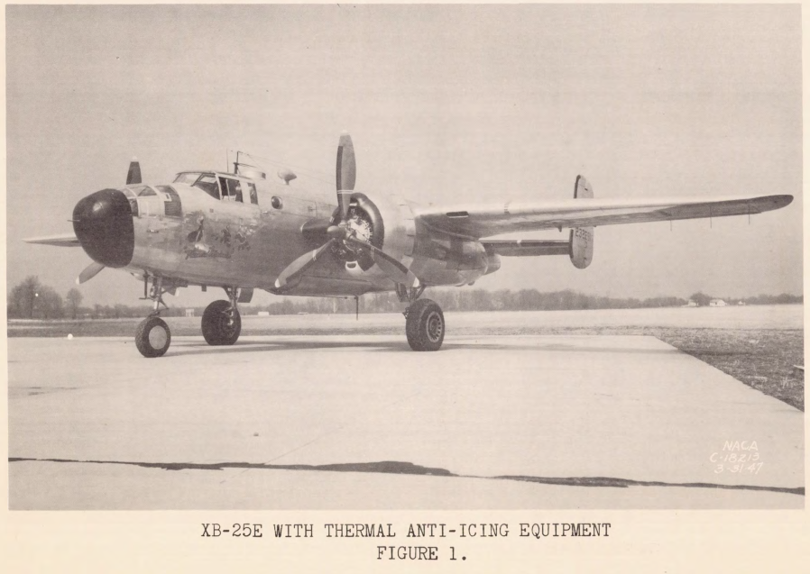
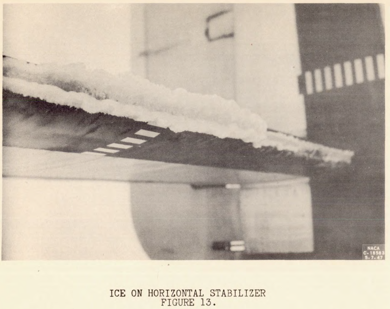
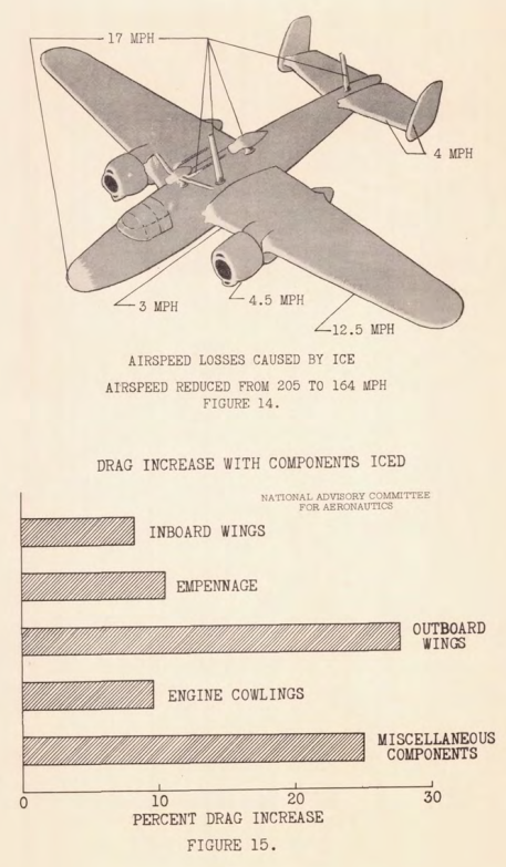
For more information see Ice Shapes and Their Effects.
PROPELLER ICE PROTECTION BY MEANS OF HOT GASES IN HOLLOW BLADES. By VERNON H. GRAY, Cleveland, Ohio
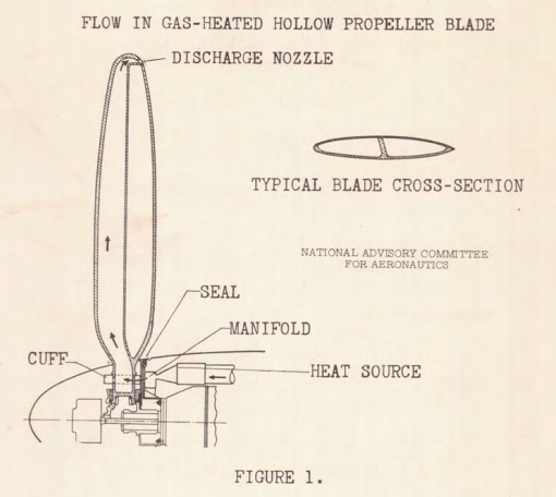
Gas-heated hollow propellers have recently been investigated both analytically end experimentally (references 1 to 5) to determine the ice-prevention effectiveness of this method of blade heating. A typical schematic flow diagram for a gas-heated propeller is shown in figure 1.
The gas is first heated in a suitable heat source and passes through a manifold and a collector ring to cuffs located on the blade shanks. The gas then flows radially outward through the hollow blade, which may have internal partitions to confine the flow to the forward portion of the blade, as shown in the cross section (fig. 1). The gas leaves the blade through a discharge nozzle at the blade tip.
The analytical investigation developed a method for determining the required initial gas temperature and flow rate for maintaining surface temperatures on all parts of the heated blade area of at least 32° F. Two previous theoretical investigations upon which parts of this analysis are based are reported in references 6 and 7.
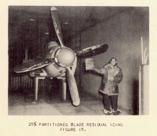
The experimental investigation obtained surface temperatures and icing data for three types of propeller blade subjected to icing conditions in the icing research tunnel, Three types of blade investigated were (1) hollow unpartitioned blades; (2) blades with radial partitions located at 50 percent of chord; and (3) blades with partitions at 25 percent of chord, The partitioned blades were investigated to determine the extent of heat flow savings.
...
CONCLUSIONS
From the experimental investigation described, the following conclusions are made: Unpartitioned blades similar to those investigated will give adequate ice protection with a minimum heat input of 40,000 Btu per hour per blade; 50 percent partitioned blades with a heat input of 14,000 Btu per hour provide marginal ice protection, with an indicated need of 20,000 Btu per hour for adequate ice protection. The 25 percent partitioned blades investigated were underheated to an extent that no safe value of heat input was indicated that would with certainly preclude ice formations aft of the heated area.
From the analysis presented, it can be concluded that gas-heated propeller blades with carefully designed internal passages will provide better chordwise and radialwise ice protection than external blade shoes for comparable heat input values. In addition, gas-heated blades will not disturb the airfoil contour or be subject to damage by erosion.
For more information see Compressed Air Heat.
ELECTRO-THERMAL METHODS OF PROPELLER ICE PROTECTION. I - CYCLICAL DE-ICING BY EXTERNAL AND INTERNAL BLADE HEATERS. By J. P. LEWIS, Cleveland, Ohio
A number of investigations has been made to obtain a solution to the problem of the protection of propellers in icing conditions.
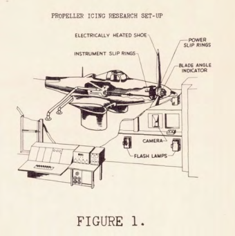
In the past, partial protection has been obtained by the use of pastes, lacquers, and alcohol in conjunction with blade feed shoes None of these methods provided adequate and positive protection and, with the development of thermal de-icing systems for the vest of tho airplane, attention has centered on the development of a thermal system for propellers. Two general methods for the thermal protection of propellers have been proposed; the first system employs electrical heating of ths blades, and in the second system a hot gas is used 28 described by Gray. This paper discusses the electro-thermal system and reports the results obtained from an investigation of two types of electrically heated propellers in tho NACA Cleveland icing research tunnel.
The development of an electrical system for propellers began as early as 1936 (reference 1). Initial investigations and analyses shoved the practicability and advantages of such a system of ice protection. Much of the early work was concerned with the details of the development of practical blade heaters and a power supply system with much of the experimental data being of a limited and inconclusive nature (reference 2). A considerable amount of experience and data were obtained by flights in natural and simulated icing conditions at the Ice Research Base, Minneapolis, Minnesota (reference 3). Investigations were conducted with two types of external-blade heater, one of wutch consisted of a rubber wire-insert blade shoe, whereas the second heater consisted of conductive rubber. From these investigations a minimum power input of 2.5 Watts per square inch was recommended with the heated arcs extending to 20 percent of chord and 90 percent of the blade radius. Those early investigations wore primarily concerned with continuous heating of the blades to obtain lce prevention rather than de-icing, In addition ihe Lack of suitable instrumentation prevented a definition and correlation of the icing conditions encountered.
Following these tests an analytical investigation of the mower requirements for a thermal-electric system (reference 4) determined power input for ice prevention of 1700 watts, per blade, which is equivalent to an average power density of 6 3/4 watts per square inch. For ice removal a power of 800 watts per blade was required, which is equivalent to an average pover density of 3.2 watts per square inch.
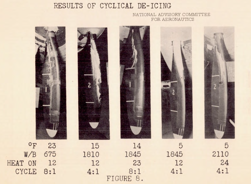
The indicated power requirement for continuous heating was in excess of that available on current aircraft. As a result, attention centered on the development of a cyclical or intermittent beating system. In this system the blades ore allowed to ice and heat is then applied for a limited period to remove the ice deposit, the cycle is then repeated. In addition to the power economics obtained, cyclical heating was also presented as a solution to the problem of runback and refreezing.
Some of the important requirements for a cyclical de-icing system may be stated as follows: The ice removal must be prompt and complete with a minimum expenditure of power. The icing allowed during the heat-off period must not impair the aerodynamic performance of the propeller. The throw-off of ice during heating must bo such that a low vibration level is maintained, no damage is suffered by the rest of the aircraft, and there is a minimum of discomfort to the passengers. The investigations of electro-thermal methods of propeller ice protection in the icing research tunnel (references 5 and 6) were primarily concerned with the determination of the power distribution and cycle time requirements for cyclical blade heating.
...
CONCLUSIONS
The results of the investigation of electrical blade heaters indicate that several important conclusions can be made as to the requirements for the design and operation of such systems of propeller ice protection.
The maximum heated areas should be at least equal to the maximum ice-covered area. For the propeller with the external heaters this maximum are extended a distance of 4 inches on both faces at the shank, tapering to approximately 1 inch at the tip. Similar although slightly greater arcas were indicated for tho internally heated blade. The minimum heated area depends upon the effect of residual ice formations on propeller performance and the allowable tolerance of such performance losses.
For cyclical de-icing a power distribution approaching chordwise uniformity is indicated, For ice prevention, however, a concentration of heat at the leading edge is required. The radial extent and distribution of heat will depend chiefly upon the propeller operating conditions. The power density is a function of the ambient-air temperature and heating time. For heating times of less than 40 seconds, power densities of 5 to 10 watts por square inch are required for corresponding ambient temperatures of 25° to 0° F.
For the external heater, heating times of 12 to 30 seconds, depending upon power input and temperature are required. A cycle time four times tho length of the heating period gave the best results for both heaters. With the internal heater a minimum heating time of 25 to 30 seconds is required.
By comparing the two types of heater, it can be seen that each has certain advantages and disadvantages. Thw external heater can bo applied to all types of blades, both hollow and solid. Compared with the internal heater, the external heater has less thermal lag which results in a quicker ice removal with less danger of runback. The main disadvantage of the external heater is its susceptibility to wear and damage from abrasion. Experience has indicated that this abrasion damage may limit the radial coverage to approximately 65 percent of the blade radius. An installation with an internal heater suffers no aerodynamic penalties resulting from an external shoe and in addition is free from abrasion trouble. With the internal heater care must be taken in the disposition of the heater elements to obtain tic correct heat distribution on the external surface, and in this respect it resembles the gas-heated blade. Compared with the hot-gas system, electrical de-icing has less thermal lag requiring little warm up and in general requires a less complicated heat supply system.
For more information see Electrothermal Ice Protection.
ELECTRO-THERMAL METHODS OF PROPELLER ICE PROTECTION. II - SERVICE EXPERIENCE WITH ELECTRICAL BLADE HEATERS IN NACA FLIGHT OPERATIONS. By GERARD J. PESMAN, Cleveland, Ohio
Information concerning the service performance of electrical propeller anti-icing systems is not plentiful; accordingly, a review of the service experience of NACA flight groups with such equipment during the winter of 1946-1947 is presented. The information was taken from service records of airplanes used for icing research end from interviews with service personnel and personnel who actually participated in the research flights. During these flights the airplanes were deliberately flown into the worst icing conditions that could be found.
The data presented are not the results of research programs and should therefore be considered as only qualitative indications of the service to be expected from such equipment in commercial service.
...
SUMMARY OF RESULTS
A study of the service records and service performance of electro-thermal anti-icing systems for propellers installed on NACA icing research airplanes during the winter of 1946-1947 gave the following qualitative results:
1. A heat concentration of 4.8 watts per square inch on the leading edge and 2.4 on the camber faces of the propeller blades was insufficient for satisfactory anti-icing at an atmospheric liquid-water content of 0.42 gram per cubic meter.
2. A heat concentration of 5.25 watts per square inch on the leading edge and 3.50 watts on the camber faces of the propeller blades was satisfactory in atmospheric liquid-water content to 0.415 gram per cubic meter.
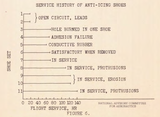
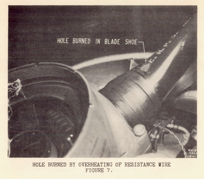
3. Service troubles with the blade shoes included open or short circuits in the leads, breakage of heating-element wires, and poor adhesion of the shoes to the propeller blades.
4. Possible future trouble with blade shoes may be leading-edge erosion and eroding of protrusions caused by buckling of resistance wires leading to exposure of these wires.
5. The propeller-hub generators have insufficient capacity to take care of their present load and have design faults that must be corrected.
This is a unique presentation, and I have not found similar NACA information published.
Notes
-
Anon: NACA Conference on Aircraft Ice Prevention A Compilation of Papers Presented by NACA Staff Members. 6505/NACA-1947/8, 1947. apps.dtic.mil ↩