"... the power required for ice prevention may be excessive for certain applications, although sufficient power for some degree of ice removal may be provided readily." 1
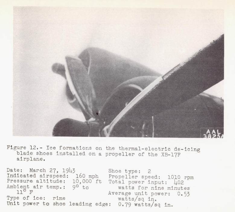
Figure 12 of NACA-ARR-4A20.
Summary
Electrothermal deicing is studied in the NACA-era.
Key Points
- The power levels required for continuous anti-ice are challenging, so deicing was persued.
- Runback ice and residual ice are challenges for deicing.
- Analogue computers calculated transient heating and deicing.
- A chordwise-sequenced zone heating ice shedding strategy was devised.
- The current 787 jet aircraft uses electrothermal heating for wing anti-icing and de-icing.
Discussion
The electric powered deicing of propeller blades, as well as wing leading edges, was studied by NACA.
The deicing of propellers is perhaps easier in some ways, as the centrifugal of the spin greatly aids the shedding of ice. Also, there are scale differences, as a wing airfoil usually has a larger chord length than a propeller. However, there are commonalities and some of the lessons learned may apply to each.
It is noted in "We Freeze to Please": A History of NASA's Icing Research Tunnel and the Quest for Flight Safety that by 1943 NACA had aircraft with robust ice protection which enabled more extensive icing flight research, and that capability was used to improve propeller deicing.
"Tests of Thermal-Electric De-Icing Equipment for Propellers", NACA-ARR-4A20 2
SUMMARY
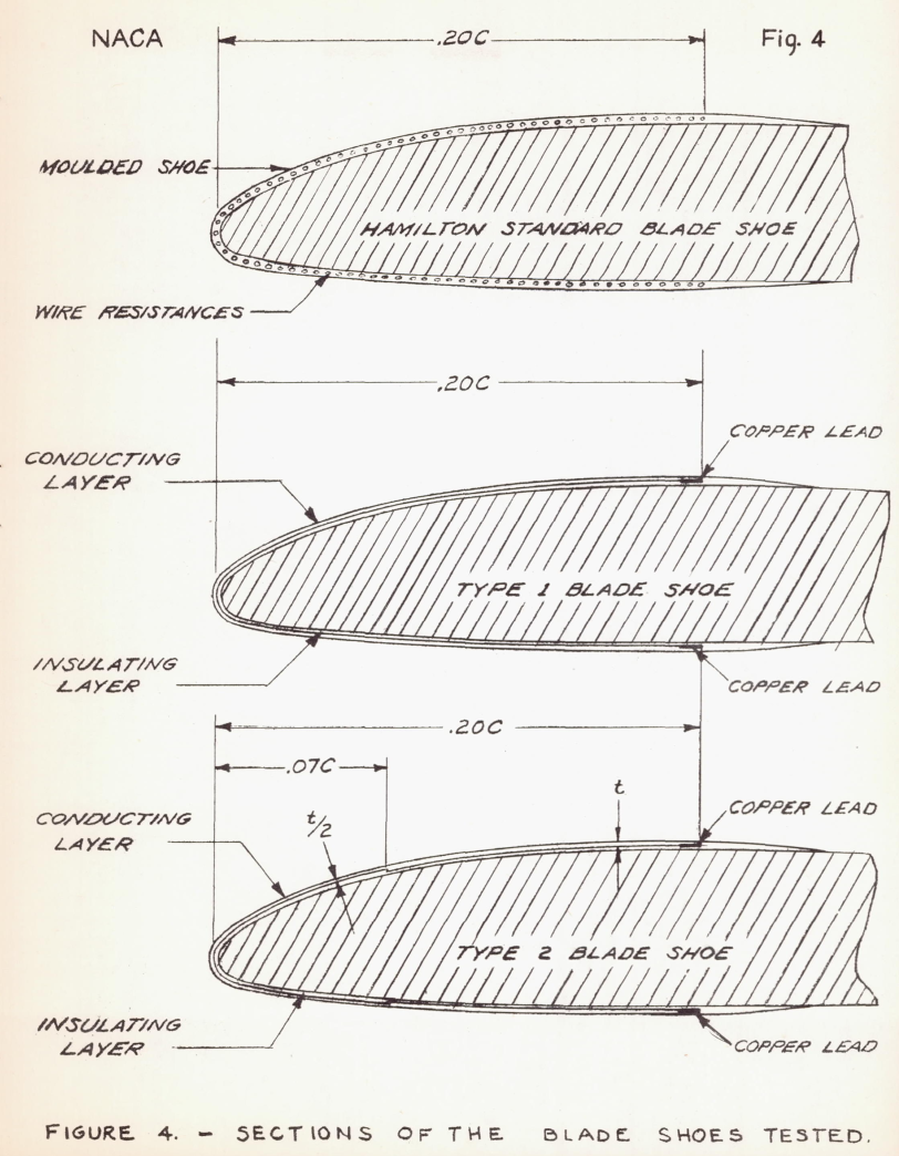
Flights were made in natural icing conditions at the NACA Ice Research Project, Minneapolis, Minn. to test several designs of thermal-electric propeller de-icing blade shoes and a hub-generator design. It was found that a minimum average unit power of 2.5 watts per square inch of blade-shoe area would protect the propeller blades at the test conditions. The most satisfactory blade shoe of the three designs tested extended to the 20-percent chord point and to 90 percent of the blade radius. A concentration of heat in the leading-edge region of this shoe was found to reduce the power input necessary for satisfactory de-icing. A satisfactory thermal design of blade shoe and a hub generator of sufficient capacity were developed.
In the second set of blade shoes manufactured by the Goodrich company, designated as shoe type 2, the radial heat distribution was uniform, but in the chordwise direction the heat was concentrated over tha leading-edge region (approximately the forward 7 percnt of the blade chord) of the blade-shoe area. This heat distribution was obtained by a change in thickness and hence in resistance of the conductive neoprene layer. The blade area protected by the types 1 and 2 blade shoes was the same, and the power inputs to the to types of Goodrich blade shoe were equal at the same line voltage.
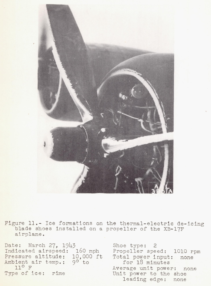
The results of tests with the Goodrich type 2 blade shoes are shown in figures 11 to 16. All the tests were run in the same icing condition, which was considered to be of uniform severity. Figure 11 shows the ice accretions on the test propeller, on the XB-17F airplane after 18 minutes in the icing condition with no heat supplied to the blade shoes. Figure 12 indicates that a supply of 402 watts to the blade shoe may have been enough to start the ice~removal process, since the ice on the inner portion of the far blade and parts of the ice on the near blade have been thrown off. The location on the near blade at which the ice has been thrown off has started to ice again, indicating that there is some time interval between the shedding of ice on the various portions of the blade. The shank of the far blade is clear, indicating recent de-icing. The condition of the blade leading edge indicates that the total power input to the three blade-shoes was too low and allowed excessive ice.
CONCLUDING REMARKS
The tests indicate that the final design of blade shoe tested (type 2) and the 2000-watt hub-generator combination will de-ice the test propeller blades in icing conditions similar to those encountered and should, after service tests, provide an acceptable means of propeller de-icing.
Pending further tests, the following design principles are recommended:
1. A minimum average unit power input of 2.5 watts per square inch of blade-shoe area should be provided for blade shoes covering the leading-edge 20-percent chord and 90 percent of the blade radius. 2. The heat distribution should be such that the unit heating supplied to the leading-edge 7-percent chord is twice that supplied to the remainder of the blade-shoe area.
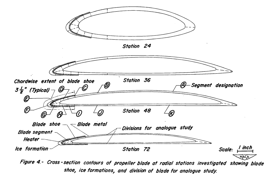
"An Investigation Utilizing an Electrical Analogue of Cyclic De-Icing of a Hollow Steel Propeller with an External Blade Shoe", NACA-TN-2852 3
SUMMARY
A study has been made of the heat requirement for the cyclic de-icing of hollow steel propellers fitted with external blade heating shoes. Solutions to the equations for the heat flow in cyclic heating of propellers were obtained, using an electrical analogy. The study showed how the energy requirement for propeller de-icing with existing blade shoes could be decreased, and illustrated the effect of blade-shoe design on the energy requirement. It was demonstrated, for example, that by increasing the heating intensity and decreasing the heating period from those currently used the energy requirement could be decreased in the order of 60 percent. In addition, ft was shown that heating requirements could be decreased further, by as much as 60 percent, through proper design of the shoes. The investigation also showed the energy requirement to increase with decreasing liquid-water content and air temperature. Uncertainties as to the exact values of convective heat-transfer coefficient prevailing over the surface of the blade and ice layer resulted in uncertainties of approximately proportional magnitude in the values of required heating intensity.INTRODUCTION
Propeller ice protection for aircraft is generally provided by electrical heating. In the development of external heating shoes, emphasis was placed primarily on the determination of the heating intensity required. Preliminary tests indicated power requirements for continuous heating to be so large that cyclic operation, with attendant power savings, was almost mandatory. Subsequent tests (reference 1) included some variation in cyclic time and other pertinent factors, but were mainly concerned with heating pattern and heating intensity for one blade and shoe configuration.
Tests of cyclically operated propeller blade shoes have been too limited in scope to provide a comprehensive picture of the effects of various parameters on blade-shoe performance. Electrical simulation of the flow of heat from the heating element of a blade shoe during cyclic operation offered a means for obtaining more complete data on cyclic de-icing. By use of an electrical analogy, a large range of configura- tions and operating conditions could be covered readily. Such a study of a similar problem was first made by Tribus (reference 2). This work was limited in it scope, reproducing portions of the data obtained in reference 1 and covering only the general aspects of the problem.DESCRIPTION OF EQUIPMENT
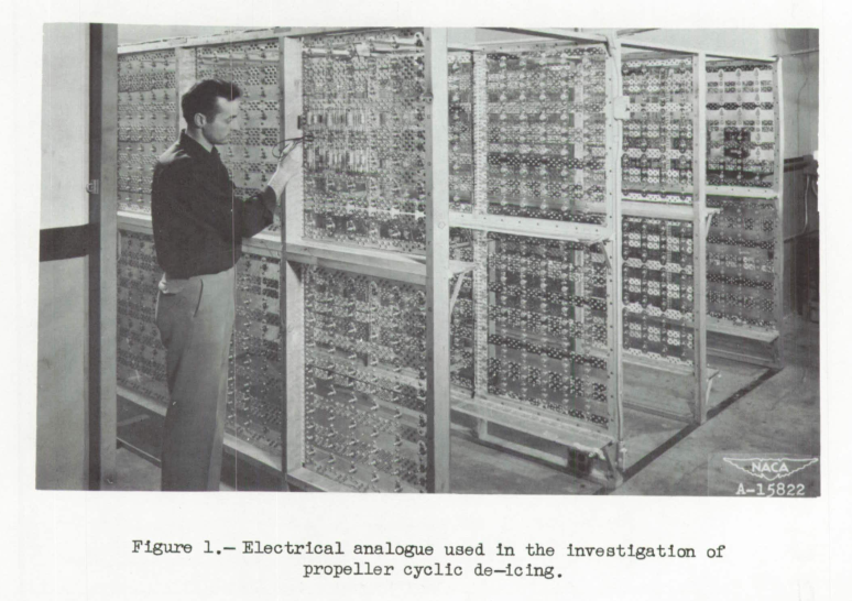
Electrical Analogue
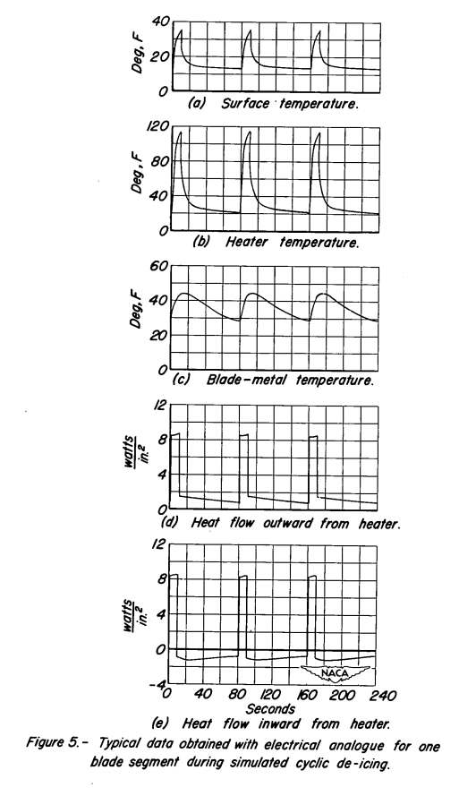
The electrical analogue used. in the study of cyclic de-icing is shown in figure 1. The analogue consists essentially of a network of electrical resistances and capacitances connected in such a manner as to simulate a thermal circuit. In the electrical circuit, electrical resistance and capacitance represent thermal resistance and capacitance, current flow represents heat flow, and voltage difference represents temperature difference. The resistances of the analogue network consist of potentiometers connected as rheostats, while the capacitances consist of condensers which were connected to obtain the desired values. The method of utilizing an electrical analogy for the solution of transient heat-flow problems is thoroughly treated in references 3, 11, and 5.
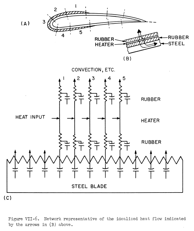
"Modern Icing Technology" by Tribus 4, while not referenced by NACA-TN-2852, (his 1949 thesis was referenced) has a figure to illustrate the type of analog circuits:
Special Circuits
Intermittent application of current, representative of cyclic heating, was accomplished by means of a switching system actuated by a synchronous electric motor. Since the power input to the blade shoe is constant during the heating part of the cycle, a source of constant current was provided for the electrical simulation of power input to the heater element. Additional constant-current circuits were arranged to represent the application of heat at the blade surface resulting from aerodynamic heating and release of the heat of fusion of the supercooled drops impinging on the blade surface as they solidified to ice.
To represent the periodic accumulation of ice on the blade shoe, relay circuits were employed which switched in resistors and condensers representing the equivalent values of thermal resistance and capacitance of the ice layers. The continuous growth of the ice formation was represented in the analogy, using the assumption that the ice built up in three layers of equal volume throughout each cycle. Periodic precharging of these condensers, just prior to their connection into the circuit, to represent the increase in temperature of the ice layers due to the addition of aerodynamic heating and release of the heat of fusion of the ice upon formation was achieved by means of a circuit utilizing the constant-current power supply and the ice-accumulation relays. These relays were synchronized with the cyclic heating through the same switching system.
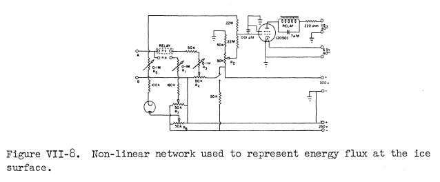
Because during application of heat certain portions of the blade-shoe surface underneath the ice formation reached the melting point of ice before release of the formation, special circuits, termed "heat-of-fusion circuits," were provided which held the surface temperature of these regions at a constant voltage representing 32 F until release of the ice accumulation. This represented the absorption of heat by the ice layer during the melting process.
"Modern Icing Technology" has two figures to illustrate this type of analog circuit:
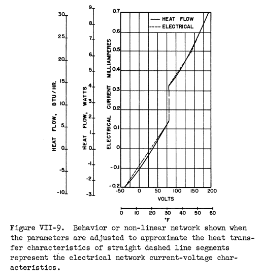
(I believe that "Behavior or non-linear..." is a typo,
perhaps "Behavior of non-linear..." was intended.)
CONCLUSIONS
The following conclusions have been reached as the result of an analytical study of cyclic de-icing with blade heating shoes mounted on a hollow steel propeller. The percentage values of energy saving presented apply directly only to the case of hollow steel blades of approximately the same configuration as that tested. However, the general conclusions are applicable to all propeller blades fitted with external heating shoes. All cyclic heating durations are based on a total cycle time of 80 seconds.
1. Considerable saving of energy can be effected with blade shoes currently in operation by applying higher heating intensities for shorter durations of time than are generally in use. For the case of conventional shoes of the type commonly used, by operating at a 5-second duration of heating time, the total energy can be decreased to about 40 percent of that required for operation at a 20-second heating duration.
2. Considerable saving of energy can be effected through proper design of blade shoes. For example, if the thickness of the insulation layer above the heater of a conventional blade shoe is decreased by a factor of 2 and the thickness of the insulation below the heater is doubled, the energy can be decreased to about 70 percent of that required for a conventional shoe operated at the same cyclic ratios. Through appropriate design and selection of insulating materials, the energy requirement can be decreased to a value approaching 38 percent of that needed for a conventional shoe operated at 5-seconds heating time.
3. The maximum heater temperatures reached under conditions of efficient de-icing for the above cases are relatively independent of heating intensity, and are well within safe limits of operation for existing insulation materials.
4. As the liquid-water content of the air stream increases, the energy required to remove ice from the propeller decreases. Meteorological conditions which impose the most stringent heating requirements on a cyclically heated propeller are low values of liquid-water content together with low air temperatures.
5. Uncertainties as to the exact values of convective heat-transfer coefficient prevailing over the surface of the blade and ice layer result in uncertainties of approximately proportional magnitude in the values of required heating intensity.
Decreasing the insulation thickness above the heater may increase thermal performance, but there are limits. The durability is generally reduced as the insulation thickness gets thinner. Rain erosion is a challenge for propellers, and wing leading edges at jet airspeed. Some designs incorporate a metal erosion shield on the outer surface.
Uncertainties about heat transfer coefficients continue to this day. NACA-TN-2852 assumed a +/-20% uncertainty, which is probably optimistic. If one's design and analysis are not robust to at least that range of variation, perhaps one should reconsider the design.
"Preliminary Investigation of Cyclic De-Icing of an Airfoil Using an External Electric Heater", NACA-RM-E51J30 5
While there are similarities between deicing on an propeller and an large airfoil, the lack of centrifugal force and size can make deicing an airfoil more challenging.
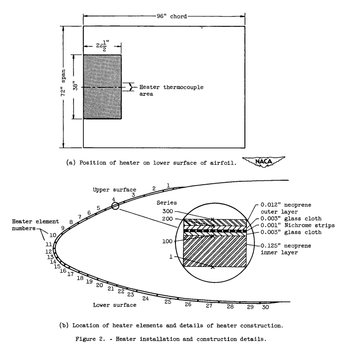
For this test, a large airfoil with many individually controlled heaters strips was used.
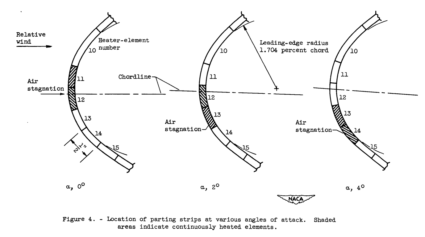
The stagnation line moves on an airfoil as flight conditions change.
This can be addressed either by a large parting strip are to cover all cases,
or re-assigning individual heater to the parting strip function
as conditions change.
Limiting the amount of runback ice is a challenge. As some liquid water forms in the deicing process, that water is available to runback and form ice.
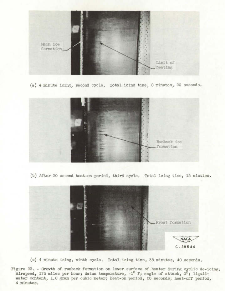
Typical de-icing and growth of the runback formation are shown in figure 22. The pictures were taken during cyclic operation through transparent sections in the tunnel side walls and show the lower surface on the airfoil with the limit of heating indicated.
The ice formation after 8 minutes and 20 seconds, or just before the second heat-on period, is illustrated in figure 22(a). The main ice formation is shown and very slight amounts of runback ice may be seen on the unheated portion of the heater. The next picture, figure 22(b), taken after the third heat-on period, shows the removal of the main ice formation and a slight increase in runback ice. Figure 22(c), taken just before the ninth heat-on period, shows that the runback formation has increased in size although very little in extent. The frost formations that have started to form downstream of the heated area are typical of those obtained in all tests and appear to be inherent to tunnel operation. These frost formations increased in size and extent with increasing amounts of runback and residual ice.
See The Effects of Humidity in Icing Wind Tunnel Tests for more on frost formations.
SUMMARY OF RESULTS AND CONCLUSIONS
For the range of variables investigated, the following results and conclusions may be stated:
1. A continuously heated parting strip in conjunction with cyclic heating was found necessary to insure quick, complete, and. consistent ice removal. A 1-inch-wide continuously heated strip at the leading edge was sufficient for the range of datum temperatures from 19° to -11° F.
2. The most important variables in determining the cyclic power requirements are the datum temperature and the heat-on time; the heat- off time, the liquid-water content, and the droplet size have a second- order effect, and the angle of attack has no appreciable effect.
3. For the most efficient removal of ice, minimum runback ice, and minimum total energy input, the condition of high local power density and short (less than 15 seconds) heating period gave the best results.
4. The optimum cycled heat input distribution pattern consisted of a uniform power density for the region of water impingement. Extensive heating beyond the impingement region did not aid materially in de-icing performance or in eliminating runback ice.
5. The experimental heater was found to have a rather low thermal efficiency. Better de-icing performance and further economies in the energy requirement would be obtained using a heater having a lower thermal capacity and a smaller thermal resistance between the heater elements and the outer surface.
6. Ice removal did not take place on attainment of a heater surface temperature of 32° F. For complete ice removal, peak surface temperatures of approximately 50° to 100° F resulted with a finite but undetermined water film formed underneath the ice formation.
Item 6 is a key point. In some colder areas, the ice may remain attached, while most other areas are well above the melting point. There is an opportunity for much melting and runback formation while waiting for the last attached areas to melt and shed. Ice can be surprisingly strong, with even "thin" ice able to bridge apparently widely spaced contact adhesion points.
"De-Icing and Runback Characteristics of Three Cyclic Electric, External Deicing Boots Employing Chordwise Shedding", NACA-RM-E53C26 6
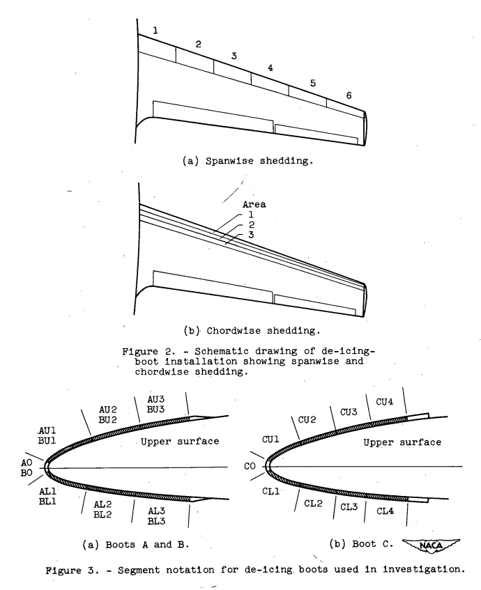
Whereas previous NACA investigations of cyclic de-icing have all employed, models using the principle of spanwise shedding, the boots included in this investigation employed the principle of chordwise shedding of ice. Chordwise shedding differs from spanwise shedding only in the manner in which the cycled portions of the boot are divided into segments. A sketch showing two hypothetical de-icing-boot installations on the wing of the same fighter-type jet aircraft is shown In figure 2. The boot shown in figure 2(a) provides spanwise shedding of ice, whereas the boot installation shown in figure 2(b) provides chordwise shedding.
If the boots are assumed to be comparable in every respect, the boot employing spanwise shedding might operate as follows: Heat is first applied to cycled area 1 (upper and lower surface) for a specified period of time. When heat is discontinued on area 1, it is immediately applied to area 2; proceeding in a spanwise direction until all areas have been heated. For the case of chordwise shedding (fig. 2(b)), the boat is divided into six segments distributed three on the upper and three on the lower surface of the airfoil. Heat might again be applied first to area 1, then to area 2, and so forth, progressing in a chordwise direction across the upper surface of the airfoil and then in like manner across the lower surface.
For purposes of identification throughout this report, the three boots employed in the investigation are labeled A, B, and C, and the cycled segments of each boot are labeled as shown in figure 3. The first letter of the segment notation (A, B, or C) denotes the boot which contains the segment; the second letter (u or L) denotes upper or lower surface; and the number in the segment notation indicates the relative position of the segment with respect to the parting strip. For example, segment BU2 is the second segment of boot B aft of the parting strip on the upper surface of the airfoil.
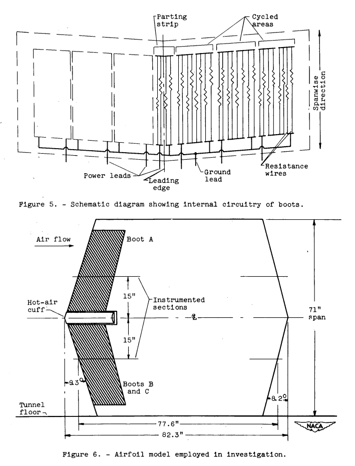
The internal circuitry of the boots was quite similar. The circuitry of each segment of each boot (including the parting strip) was arranged in a series-parallel circuit as shown by the schematic diagram presented In figure 5. For boots B and C, several sets of individual heater wires arranged in parallel were wound back and forth spanwise in each segment of the boot. At the spanwise end of each segment, the wires were fastened to electrically conductive strips. In general, the method of construction employed for boot A was similar to that employed for boots B and C, except that in this case, the sets of wires ran back and forth chordwise and were fastened to bus bars which ran in a spanwise direction (see fig. 4). The location of bus bars shown in figure 5 is representative of boots B and C. All segments of the boots were internally connected to a common ground.
The model employed in the icing investigation of the various boots was an NACA 65-213 airfoil section having a 9.3° leading-edge sweepback, an 82.3-inch chord at the center line, and a 71-inch total span. The model is symmetrical about the center line and was mounted vertically in the 6- by 9-foot test section of the icing research tunnel. The airfoil was constructed similarly to an actual wing section of the particular fighter-type jet airplane for which the boots were designed and, hence, incorporated taper in addition to the leading-edge sweepback. A schematic drawing of the model employed in the investigation is shown in figure 6.
General De-Icing and Runback Characteristics
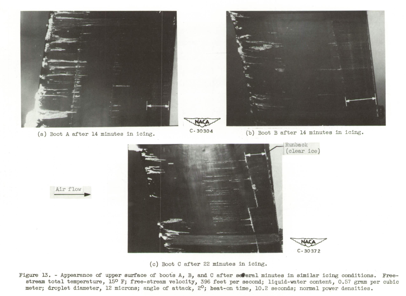
The icing and runback characteristics of boots A, B, and C operating with the local surface temperatures and the temperature distributions presented in figures 7 and 8 are shown in figure 13. The photographs show the appearance of the upper surface of the boots after 14 and 22 minutes in the following icing conditions: free-stream total temperature, 15° F; free-stream velocity, 396 feet per second; liquid-water content, 0.57 grain per cubic meter; and angle of attack, 2°. It is apparent that, for these icing conditions, none of the boots provide complete shedding of ice from the surface for operation at design power densities and heat-on time. For longer periods of time in the abovementioned icing condition, the amount of ice adhering to boots B and C remained relatively unchanged, while the amount of ice adhering to boot A increased slightly, which indicated that boot A provides only marginal icing protection for the condition listed. The photographs showing boots A and B indicate the amount of residual ice after the application of heat to segments AU3 and BU3. The photograph of boot C was taken the instant heat was discontinued on segment CU2 and applied to segment CU3. The ice adhering to segments CU3 and CU4 shed clean when heat was applied to these segments.
The photographs shown in figure 13 are typical of the comparative de-icing characteristics of the boots operating in similar icing conditions. In general, for the icing conditions investigated, no appreciable differences in the performance characteristics of boots B and C were observed. Boot B had a fine-textured clothlike surface as compared with the smoother surface of boot C, but this slight difference in surface roughness had little or no effect on ice removal. As evidenced in figure 13, the amount of icing protection afforded by boot A was slightly lower than that of the other two boots; and, hence, the boot provides marginal protection at a slightly higher value of free-stream temperature than does boot B or C, other conditions being equal. In general, for a free-stream velocity of about 395 feet per second, an angle of attack of 2°, and a liquid-water content of 0.5 to 0.6 grain per cubic meter, the range of free-stream total temperatures at which the icing protection afforded by the various boots became marginal was from 12° to 15° F. The slightly lower performance characteristics observed for boot A are attributable to the internal construction of the boot. The presence of rather large bus bars (which act as heat sinks), small unheated areas between all cycled segments, and heater wires running parallel to the airflow at 1/8-inch spacing all contribute to local cold spots from which ice fails to shed during heat-on time. The ice adhering between segments of boot A (fig. 13) is typical of the icing characteristics of the boot. In some cases the ice adhering between segments formed ahead of and behind the small unheated areas between segments to a length of 1 inch or more without adhering to the heated areas. In figure 13(a) it can be noted that considerable ice has formed on the unheated area between the parting strip and the forward cycled segment.
A comparison of figures 13(a), (b), and (c) shows that the runback pattern obtained for the boots in the icing condition listed is quite similar, with no runback occurring on the aluminum skin behind, the boot scarf. The runback is a smooth clear ice formation not exceeding 1/8 inch in thickness on the upper surface.
As a result of the icing investigation, it was found that the forward cycled segments, upper, and lower surfaces, were the most critical areas for the three boots investigated. Bridging of the parting strip occurred at the more severe icing conditions included in the investigation. In some cases, parting-strip surface temperatures in excess of 75° F were recorded without effecting removal of the ice cap. Although considerable melting occurred beneath the ice cap and the resulting water melted holes through portions of the cap, the inability of the forward cycled segments to melt the bond prevented ice removal.
SUMMARY OF RESULTS
The following results were obtained from an icing investigation of three production samples of electric, cyclic de-icing boots.
1. The forward cycled segments, upper and lower surfaces, of all three boots were the most critical areas for the icing conditions investigated.
2. Unheated areas as small as 1/8 inch wide occurring in the heated surface of an external, rubber-clad, electric, cyclic de-icing-boot contributed to local cold spots on which ice forms.
3. The runback characteristics of the three boots were similar.
4. The performance characteristics of two of the three boots were very similar. The icing protection afforded by the boot having small unheated areas existing between segments was slightly less than that of the other two boots.
5. For icing conditions investigated at free-stream total temperature of 15 ° F and less, the detrimental effect of-the small amount of runback ice observed is probably small in comparison with the effect of ice adhering to the surface of the boot just aft of the parting strip because of incomplete shedding.
6. For a free-stream velocity of 395 feet per second and an angle of attack of 2°, the range of free-stream total temperatures at which the icing protection afforded by the various boots became marginal was from 12° to 15° F for the values of liquid-water content included in the investigation.
While a direct comparison was not included, chordwise shedding often results in less runback ice than spanwise shedding.
Conclusions
Electrothermal heating is still used today for propeller ice protection. Use for wing ice protection is less common, although the current 787 jet aircraft uses electrotherm wing ice protection (we will discuss that more in the upcoming "Conclusions of the Ice Protection Thread").
Electrothermal ice protection is used widely today for many smaller components, including windshields and air data probes.
Other Publications
There are other relevant publications that were not detailed herein.
Propeller blades
- Lewis, James P.: De-Icing Effectiveness of External Electric Heaters for Propeller Blades. NACA-TN-1520, 1948. ntrs.nasa.gov
- Lewis, James P., and Stevens, Howard C., Jr.: Icing and De-Icing of a Propeller with Internal Electric Blade Heaters. NACA-TN-1691, 1948. ntrs.nasa.gov
- Dallas, Thomas, and Ellisman, Carl: Analysis and Preliminary Investigation of Eddy-Current Heating for Icing Protection of Axial-Flow-Compressor Blades. NACA-RM-E9EO6, 1949. ntrs.nasa.gov
Analysis
- Scherrer, Richard: An Analytical Investigation of Thermal-Electric Means of Preventing Ice Formations on a Propeller Blade. NACA-ACR-4H31, 1944. ntrs.nasa.gov
- Neel, Carr B., Jr.: An Investigation Utilizing an Electrical Analogue of Cyclic De-Icing of a Hollow Steel Propeller with Internal Electric Heaters. NACA-TN-3025, 1953. ntrs.nasa.gov
Citations
An online search (scholar.google.com) found citations for
NACA-ACR-4H31 8 times,
NACA-ARR-4A20 7 times,
NACA-TN-1520 14 times,
NACA-TN-1691 10 times,
NACA-RM-E9EO6 2 times,
NACA-RM-E51J30 2 times,
NACA-RM-E53C26 0 times,
NACA-TN-2852 4 times, and
NACA-TN-3025 0 times.
Notes
-
Scherrer, Richard: An Analytical Investigation of Thermal-Electric Means of Preventing Ice Formations on a Propeller Blade. NACA-ACR-4H31, 1944. ntrs.nasa.gov ↩
-
Scherrer, Richard, and Rodert, Lewis A.: Tests of Thermal-Electric De-Icing Equipment for Propellers. NACA-ARR-4A20, 1944. ntrs.nasa.gov ↩
-
Neel, Carr B., Jr.: An Investigation Utilizing an Electrical Analogue of Cyclic De-Icing of a Hollow Steel Propeller with an External Blade Shoe. NACA-TN-2852, 1952. ntrs.nasa.gov ↩
-
Tribus, Myron: "Modern Icing Technology" 1952. lib.umich.edu ↩
-
Lewis, James P., and Bowden, Dean T.: Preliminary Investigation of Cyclic De-Icing of an Airfoil Using an External Electric Heater. NACA-RM-E51J30, 1952. ntrs.nasa.gov ↩
-
Ruggeri, Robert S.: De-Icing and Runback Characteristics of Three Cyclic Electric, External Deicing Boots Employing Chordwise Shedding. NACA-RM-E53C26, 1953. ntrs.nasa.gov ↩