"the most economical icing protection ... consists of a system utilizing hot gas from a convenient heat source, namely, the turbojet-engine compressor" 1
From NACA-TN-2866.
Summary
Compressed air heating becomes common for ice protection in the jet era.
Key points
- To support jet engine powered transportation, NACA had several studies of ice protection using compressed air heating.
- Deicing schemes were proposed to reduce the amount of air bled from the engines.
- Some innovative features, like continuously heated parting strips and recirculating hot air supply, did not see much use.
- Compressed air heating is used widely today for jet powered transports.
Discussion
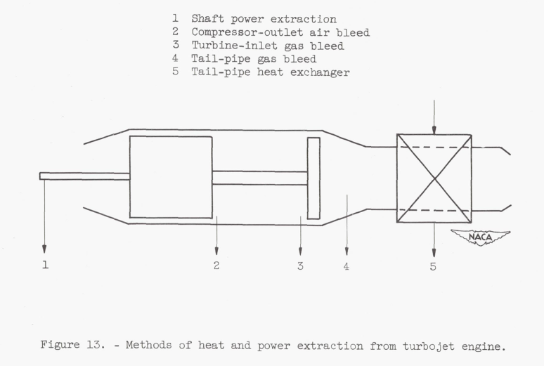
As aviation entered the jet propulsion age, reciprocating-engine exhaust heat was not an option. However, the jet engine air compressor offers an ample (but not unlimited) supply of hot, compressed air that may be bled from the engine compressor airstream for ice protection, cabin heating, and other functions.
Several NACA studies considered using compressed air heating in a deicing mode, rather than anti-icing.
NACA-RM-E51J29 1
INTRODUCTION The protection of wings and tail surfaces for high-speed, high-altitude turbojet-powered aircraft by local heating of the areas subject to icing may be accomplished by either continuous heating, or cyclical de-icing. In continuous heating, the surfaces are either raised to a temperature just sufficient to maintain the impinging water in a liquid state or are supplied sufficient heat to evaporate all the impinging water in a specified distance behind the impingement area. Past NACA research has provided basic criteria for use in the design of continuous heating systems (references 1 and 2); however, the exact type of continuous heating for an airplane component depends on a complexity of parameters and is more fully discussed in reference 3. Design analysis in reference 3 has shown that the heat requirements and associated airplane performance penalties for high-speed, high-altitude transport aircraft using continuous heating for icing protection are extremely large and in some cases may be prohibitive.
"reference 3" is:
- Hacker, P. T., Dorsch, R. G., Gelder, T. F., Lewis, J. P., Chandler, H. C., Jr., and Koutz, S. L.: Ice Protection for Turbojet Transport Airplane. S.M.F. Fund Paper No. FF-1. Presented at I.A.S. Fifth Annual Flight Propulsion. Meeting, March 24, 1950.
I have not been able to find a copy of this. However, NACA-TN-2866 2 has a similar title and shares three of the authors, so I believe that it has similar information.
Another method by which icing protection for airfoil shapes can be accomplished is by cyclical de-icing in which some ice is permitted to form on the surfaces and then is removed periodically during short, intensive applications of heat. A water film between the surface and the ice is caused by the heat application and permits removal of the ice by aerodynamic forces. Because the heating is intermittent, heat is supplied successively to relatively small surface areas; a constant heat load is thus maintained on a heat source. The total heat input for cyclical de-icing, therefore, can be greatly reduced from that required for continuous heating.
Because ice formations normally extend over the leading edge and onto both upper and lower surfaces, removal by aerodynamic forces is slow and erratic even though sufficient heat has been applied to form a water film beneath the ice. The need for a continuously heated parting strip near the leading edge of airfoils is indicated in reference 4 and unpublished NACA data. When an ice-free strip is maintained spanwise along the leading edge, the ice formation is divided into two segments, one each on the upper and lower surfaces of the airfoil, and removal by aerodynamic forces is facilitated.
DESIGN CONSIDERATIONS FOR HOT-GAS CYCLICAL DE-ICING SYSTEM
Analysis of the problems associated with the design of a hot-gas cyclical de-icing system for airfoils indicates that the following criteria should be considered:
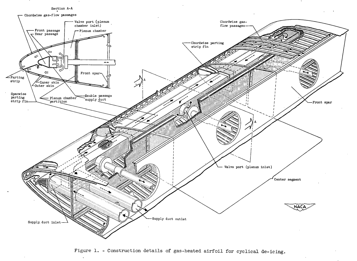
1. The surface area to be de-iced should be divided into a number of segments such that the total number of segments heated in sequence will equal the cycle ratio (total cycle time divided by heat-on period). In this manner, a constant heat load will be maintained. 2. The gas supply duct should be maintained at an elevated tempera- ture level to avoid undue thermal lag in the system. 3. A continuously heated parting strip should be provided near the leading edge in order to obtain consistent and rapid ice removal during cyclical de-icing. 4. In order to insure good ice removal and prevent ice-bridging between the various intermittently heated segments, chordwise parting strips may be desirable. 5. Insulation for the gas supply system may be desirable to reduce heat losses.A unique solution to the preceding criteria is obtained by the hot- gas cyclical de-icing system shown in figure 1. The system consists of the following principal features:
1. The gas supply system consists of a doub1e-passage duct in which high-temperature, high-pressure gas will flow outboard in a forward passage and return in a contiguous rearward passage. Throttling valves are located in the rearward passage at each of the airfoil segments to be intermittently heated. These valves are opened in spanwise sequence and thereby permit a constant flow of gas through the forward passage. The constant flow maintains the entire duct continuously heated; consequently, thermal lags in the system become negligible.
2. An ice-free spanwise parting strip near the airfoil leading edge is heated by a conductive fin connecting the outer skin with the forward passage of the gas supply duct. Because the gas supply duct is continuously heated, heat will be conducted through the fin to form a narrow, continuously heated parting strip. The width of the parting strip is governed by the operational and icing conditions; a narrows parting strip of about 0.5 to 1.0 inch is satisfactory for good ice removal and for heat economy.
Other methods for attaining a parting strip are by electric heating or by a hot-gas supply duct independent of the one supplying the intermittently heated segments; An electrically heated parting strip has all the inherent disadvantages of an electrical system, while an independent gas supply duct for the parting strip has weight disadvantages and may incur considerable heat losses.
3. Chordwise ice-free parting strips are located between adjacent intermittently heated airfoil segments. The parting strips are continuously heated by the gas supply duct in a manner similar to that used for the spanwise parting. strip.
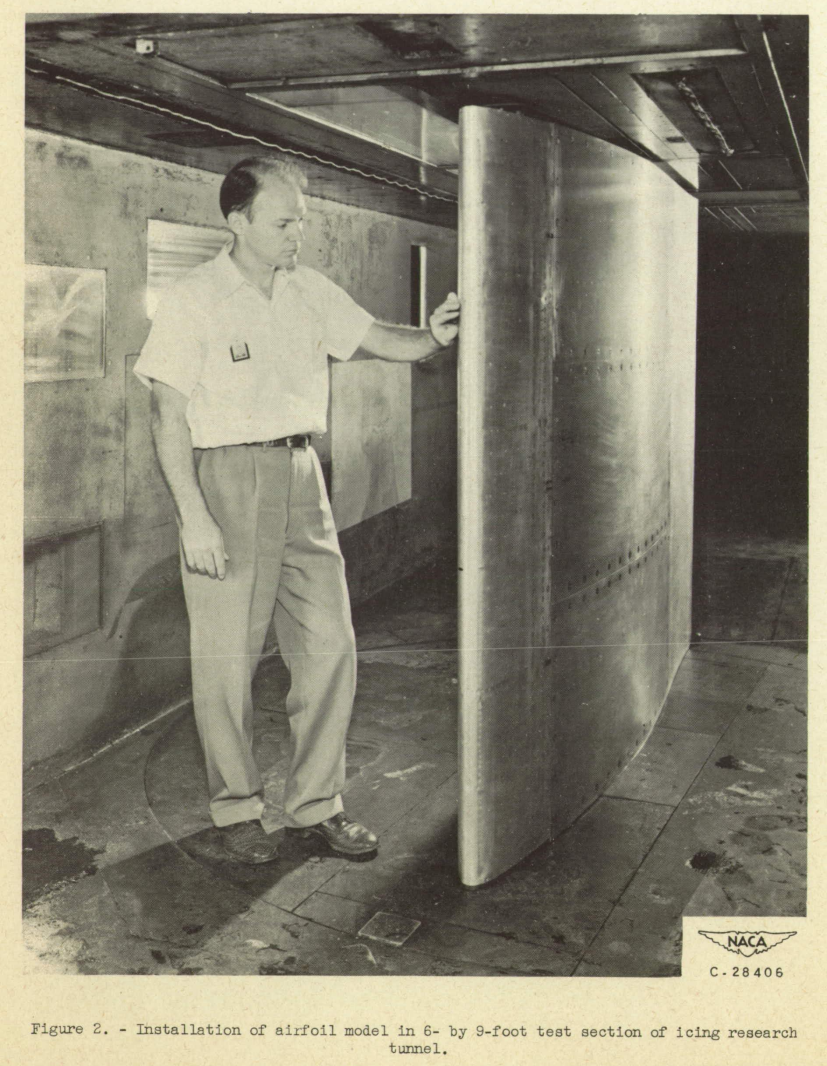
The model investigated is an NACA 651_212 airfoil section of 8-foot chord spanning the 6-foot vertical height of the Lewis icing research tunnel (fig. 2). The leading edge consisting of three spanwise segments is gas-heated to 12 percent of chord. The center segment of the wing is 3 feet in span and contains most of the instrumentation while the top and bottom segments are each 1.5 feet in span. All segments are capable of being heated independently for cyclical ice removal.
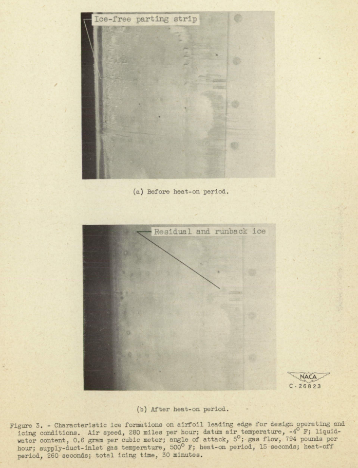
The over-all performance of the system for the design condition was found to be satisfactory at a gas flow of 800 pounds per hour, a heat-on period of 15 seconds, and heat-off period of 260 seconds. Under these conditions, the parting strip was approximately 0.75 inch wide after 258 seconds of icing (fig. 3(a)). The heavy Ice formations at the lead- ing edge were removed after 4 to 8 seconds of heating. Ice removal occurred first on the top surface while the Ice on the lower surface shed progressively aft from the parting strip. At the end of the heating period (fig. 3(b)), no ice remained on the heated area with the exception of small deposits on the last 4 inches of the heated lower surface (9 to 13 in. aft of leading edge). In this region, which is just rearward of the plenum chamber partition, runback rivulets occasionally froze and remained for two or three cycles before the larger accretions were removed.
SUMMARY OF RESULTS
The preliminary results obtained in an investigation of cyclical de-icing with a gas-heated airfoil are summarized as follows:
1. Satisfactory cyclical de-icing of an 8-foot chord NACA 651-212 series airfoil was achieved with a hot-gas system over a range of cycle ratios from 10 to 26 and utilizing a continuously gas-heated parting strip.
2. In the range of conditions investigated, the prime variables in the determination of the required heat input for cyclic ice removal were the datum air temperature and the cycle ratio; heat-off period, liquid-water content, airspeed, and angle of attack had only secondary effects on heat requirements.
3. For minimum runback, efficient ice removal, and minimum total heat input, short heat-on periods of about 15 seconds with heat-off periods of approximately 260 seconds gave the best results.
4. In general, the highest gas temperatures and flow rates usable for a given operating and icing condition resulted in the shortest heat-on periods and the best ice removal.
...
Runback and residual ice are limitations of any deicing system. If your application has strict limits on runback and residual ice, you might require anti-icing rather than deicing.
NACA-TN-2866 3
SUMMARY
The problems associated with providing icing protection for the critical components of a typical turbojet transport airplane operating over a range of probable icing conditions are analyzed and discussed. Heating requirements for several thermal methods of protection are evaluated and the airplane performance penalties associated with providing this protection from various energy sources are assessed.
The continuous heating requirements for icing protection and the associated airplane performance penalties for the turbojet transport are considerably increased over those associated with lower-speed aircraft. Experimental results show that the heating requirements can be substantially reduced by the development of a satisfactory cyclic de-icing system. The problem of providing protection can be minimized by employing a proper energy source since the airplane performance penalties vary considerably with the source of energy employed.
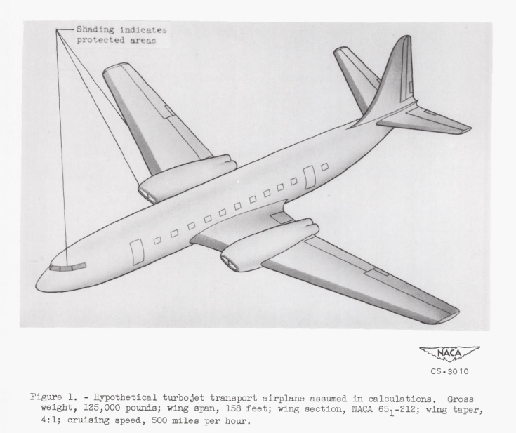
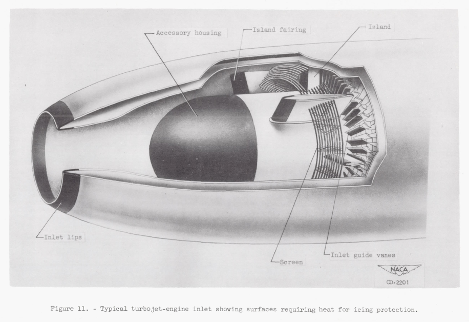
The optimum icing protection system for the turbojet transport or for any other particular aircraft cannot be generally specified; the choice of the optimum system is dependent upon the specific characteristics of the airplane and engine, the flight plan, the probable icing conditions, and the performance requirements of the aircraft.INTRODUCTION The introduction of the high-speed, high-altitude, turbine-powered airplane for all-weather operation makes necessary a new appraisal of the icing protection requirements. The unique design features and mode of operation of the turbojet airplane may result in requirements for adequate icing protection that are considerably different from conventional aircraft. In addition to operating at speed and altitude conditions differing greatly from current conventional aircraft, the turbojet airplane has a high rate of fuel consumption and a restricted flight plan. Thus, any penalties imposed upon the airplane performance by the provision and operation of the icing protection system assume great importance. These factors, together with the demand for all-weather operation, require that careful consideration be given to the problems associated with providing icing protection for the turbojet airplane. The. major problems that must be considered are: (1) the conditions of icing and the degree of protection required, (2) the method of protection and the associated protection requirements, and (3) the penalties imposed by the protection system on the airplane performance. The purpose of this report is to analyze and evaluate the icing protection problem for a high-performance turbojet transport airplane in terms of these three considerations.
This is for a turbojet engine. More recent turbofan engines have an additional fan and fan-air flow circuit. Bleed air is typically extracted from the compressor, and cooled through a heat exchanger using fan air.
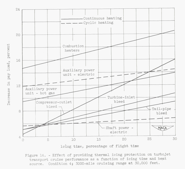
From a modern perspective, even a 4 percent reduction in payload would be onerous for commercial airline operations, and 20 percent reduction would be completely impractical.
Airplane Descent Performance
During climb and cruise the turbojet engines are operated at relatively high power levels; however, during the descent portion of the flight, it will be necessary to operate engines at much lower power levels in order that the placard dive speed of the airplane will not be exceeded. Therefore, the availability of energy from the turbojet engine during descent is considerably lower than in either climb or cruise. An electrical system operating with shaft power could provide adequate protection during descent provided the generators were designed to operate over a wide range of engine speeds. Also, turbine-inlet and tail-pipe bleed temperatures are sufficient to provide protection even at low engine speeds. Compressor-outlet temperatures are so low that protection of the complete airplane during descent by means of compressor bleed air is doubtful; however, sufficient energy may be available to prevent serious engine icing. Furthermore, it should be possible at any time during descent to level out for a short period of time, increase the engine power, and shed the ice formations.[Emphasis added.]
This is a major challenge for the proposed system. At the time, it may have been viewed as feasible, but from a modern perspective requiring a significant change in flight path would be impractical.
Adequate heating at low engine power conditions (such as descent) is still a challenge today.
CONCLUDING REMARKS
Icing protection will be required for a typical high-speed, high-altitude turbojet transport airplane operating over a probable range of icing conditions because aerodynamic heating is not sufficient to raise the temperature of an unheated surface above the freezing level. Icing protection for the turbojet airplane may be accomplished by conventional hot-gas systems, although the heating requirements and performance penalties are considerably increased from those now associated with lower-speed aircraft. Provision for this increased heat demand necessitates a critical study of its effect on the performance of the turbojet airplane, an airplane the operating criteria of which are restricted even in ideal flight conditions.
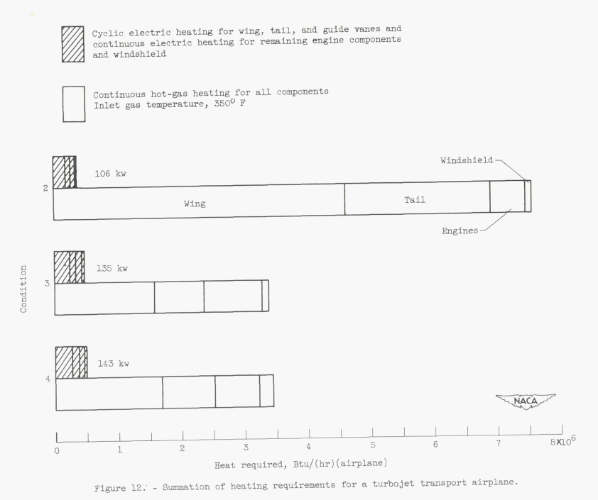
The maximum continuous hot-gas requirement for the turbojet transport occurred near 15,000 feet and is approximately 7,500,000 Btu per hour, with wing and tail protection comprising over 90 percent of this total. The airplane protection requirement can be reduced to a maximum of approximately 490,000 Btu per hour or 143 kilowatts by using a cyclic electrical de-icing system.
The problem of providing for the maximum continuous hot-gas requirement of 7,500,000 Btu per hour is minimized by employing the turbojet engine as the heat source. This large heat requirement represents approximately a 10-percent bleed of the engine air flow, assuming a 350 F initial gas temperature to the protection system. Use of a gas cyclic de-icing system should reduce these requirements by approximately 70 to 80 percent.
The airplane performance penalties chargeable to providing icing protection vary considerably with the energy source employed. The proper selection of a heat source for an aircraft icing protection system depends on several considerations such as effect on rate of climb and on pay load, amount of time expected to be in icing, and practical design limitations. On the basis of this investigation a continuous hot-gas system with compressor-discharge air appears the most attractive for short icing encounters if the high penalty on thrust or rate of climb can be tolerated. By utilizing a gas cyclic de-icing system, the climb and thrust penalties can be reduced considerably. For longer icing times, a cyclic electrical de-icing or a continuous hot-gas system with turbine-inlet or tail-pipe gas appears more feasible.
A continuous 10% bleed extraction for ice protection would be an onerous load. "Modern Icing Technology" 3 says of compressor air extraction:
The performance loss in the engine is serious. An extraction of 1 per cent of the airflow causes approximately a 2 per cent loss in thrust.
[Note that this was for the turbojets of the era. For more current turbofan jet engines, the relationship is more complex, but let us call this an order of magnitude estimate.]
It is clear that there was still much technical was development needed to achieve practical compressor bleed air heating for ice protection.
Other studies
Several preliminary studies on propeller ice protection are not detailed herein. Largely, the findings were incorporated into the later works reviewed here.
- Darsow, John F., and Selna, James: A Flight Investigation of the Thermal Performance of an Air-Heated Propeller. NACA-TN-1178, 1947. ntrs.nasa.gov
> review NACA-TN-1178 - Gray, Vernon H., and Campbell, B. G.: A Method for Estimating Heat Requirements for Ice Prevention on Gas-Heated Hollow Propeller Blades. NACA-TN-1494, 1947. ntrs.nasa.gov
- Mulholland, Donald R., and Perkins, Porter J.: Investigation of Effectiveness of Air-Heating a Hollow Steel Propeller for Protection against Icing, I - Unpartitioned Blades. NACA-TN-1586, 1948. ntrs.nasa.gov
- Perkins, Porter J., and Mulholland, Donald R.: Investigation of Effectiveness of Air-Heating a Hollow Steel Propeller for Protection against Icing, II- 50-Percent Partitioned Blades. NACA-TN-1587, 1948. ntrs.nasa.gov
- Mulholland, Donald R., and Perkins, Porter J.: Investigation of Effectiveness of Air-Heating a Hollow Steel Propeller for Protection against Icing, III - 25-Percent Partitioned Blades. NACA-TN-1588, 1948. ntrs.nasa.gov
- Gray, Vernon H.: Heat Requirements for Ice Prevention on Gas-Heated Propellers. SAE preprint No. 424 (paper presented at SAE Annual Meeting, 1950), 1950.
Three other NACA studies on compressed air heating for airfoils are worth mentioning here.
- Gray, Vernon H., and Bowden, Dean T.: Comparison of Several Methods of Cyclic De-Icing of a Gas-Heated Airfoil. NACA-RM-E53C27, 1953. ntrs.nasa.gov
> review: NACA-RM-E53C27
The same model as in NACA-RM-E51J29 was used, with some variations in the internal heating.
- Bowden, Dean T.: Investigation of Porous Gas-Heated Leading-Edge Section for Icing Protection of a Delta Wing. NACA-RM-E54I03, 1955. ntrs.nasa.gov
> review: NACA-RM-E54I03
The title is pretty descriptive.
- Gray, Vernon H., and von Glahn, Uwe H.: Heat Requirements for Ice Protection of a Cyclically Gas-Heated, 36 Swept Airfoil with Partial-Span Leading-Edge Slat. NACA-RM-E56B23, 1956. ntrs.nasa.gov
> review: NACA-RM-E56B23
This describes some considerations for getting a heat supply to a moving surface, like a leading edge slat.
Conclusions
Compressed air heating did see use in the NACA-era. Two commercial jet transports introduced near the end of the NACA-era, the Boeing 707 and the Douglas DC-8, both had engine bleed compressed air heat anti-ice for the wing leading edges and the empennage. However, I view their designs as being more influenced by industry technology development and the prior engine exhaust heat and combustion air heating designs, rather than the NACA compressed air heating studies that were occurring at around the same time. The designs did not use the cycling deicing nor the recirculating hot air supply proposed in several of the NACA studies. I characterize the industry anti-ice designs as more economical than the NACA studies. Anti-ice was used despite the NACA assessment that:
performance penalties for high-speed, high-altitude transport aircraft using continuous heating for icing protection are extremely large and in some cases may be prohibitive. 1
Compressed air heating is still commonly used in the larger jet transports for wing ice protection (the Boeing 787, with electrothermal wing ice protection, is a notable exception). It is used in some smaller aircraft, but more commonly for engine inlet ice protection. Other means of wing ice protection are sometimes used on the smaller jet transports.
Adequate heating at low engine power conditions (such as descent) is still a challenge today. Some engines and airplanes use a higher than nominal idle setting in icing conditions (set either by crew action or automatically). However, there are limits as to how much thrust can be boosted (one still has to be able to land the airplane).
Citations
An online search (scholar.google.com) found citations for
NACA-RM-E51J29 18 times,
NACA-TN-2866 19 times, and
"Modern Icing Technology" one time.
Notes
-
Gray, Vernon H., Bowden, Dean T., and von Glahn, Uwe H.: Preliminary Results of Cyclical De-icing of a Gas-Heated Airfoil. NACA-RM-E51J29, 1952. ntrs.nasa.gov ↩↩↩
-
Gelder, Thomas F., Lewis, James P., and Koutz, Stanley L.: Icing Protection for a Turbojet Transport Airplane: Heating Requirements, Methods of Protection, and Performance Penalties. NACA-TN-2866, 1953. ntrs.nasa.gov ↩
-
Tribus, Myron: "Modern Icing Technology" 1952. lib.umich.edu ↩↩