"... ice on the airplane windshield, which is known to be a problem in urgent need of solution."
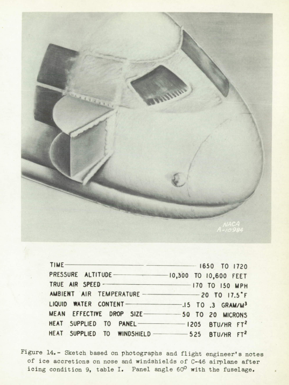
Figure 14 from NACA-TN-1434.
Summary
Ice protection for windshields matured during the NACA-era.
Key points
- In 1939: "The existing practice of making the airplane windshield retractable or removable by the pilot ... against loss of vision due to rain or ice"
- By 1947, window heat designs similar to current designs were available.
Discussion
Ice protection for windshields matured during the NACA-era.
Technology progressed from this in 1939 (NACA-SR-130):
The existing practice of making the airplane windshield retractable or removable by the pilot ... against loss of vision due to rain or ice
By 1947, there were electrical window heating ice protection designs similar to current designs (NACA-TN-1434).
"An Investigation of the Prevention of Ice on the Airplane Windshield", NACA-SR-130 1 and NACA-TN-754 2
INTRODUCTION
The National Advisory Committee for Aeronautics is conducting a program of ice research aimed to reduce the risks now attendant with airplane operations during icing conditions. A part of this program is concerned with the prevention of ice on the airplane windshield, which is known to be a problem in urgent need of solution.SUMMARY
An investigation has been completed on several methods for the prevention and removal of ice on an airplane windshield. Tests were made on the use of electric heating, hot-air heating, and an alcohol-dispensing, rotating wiper blade. The results showed that vision through the airplane windshield could be maintained during severe icing conditions by the use of heat. When put in operation prior to the formation of ice on the windshield, the rotating wiper blade prevented the formation of ice. A combination system that employs the use of heated air and a rotating wiper blade would appear to give protection against formation of ice on the windshield exterior, prevent frost on the interior, and provide for the removal of rainfall.APPARATUS Most of the tests on the models applying to various methods included in the investigation were made under simulated icing conditions in flight although some preliminary tests of the electrically heated model were made in the N.A.C.A. 7- by 3-foot ice tunnel.
We saw the N.A.C.A. 7- by 3-foot ice tunnel in the Icing Wind Tunnel Test Thread (not to be confused with the later NACA [Cleveland] Icing Research Tunnel).
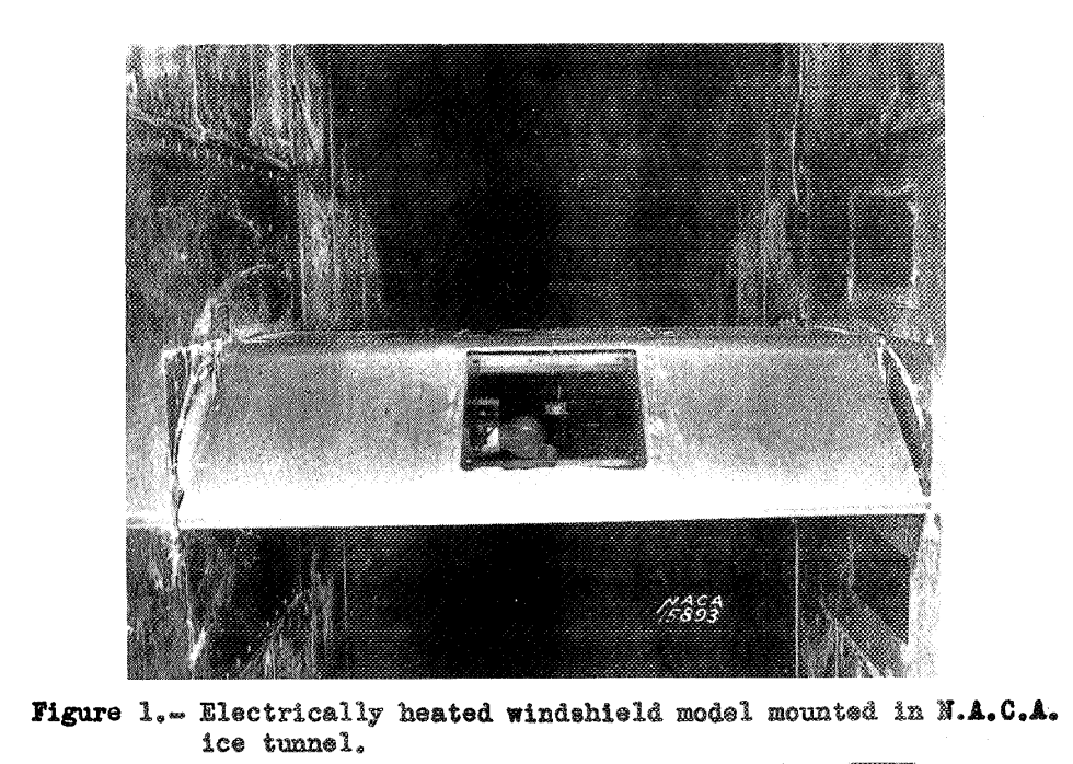
Electrically Heated Tunnel Model
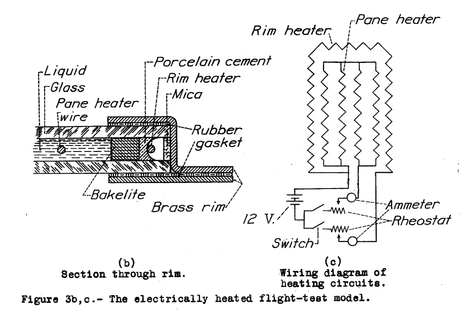
The tunnel model of the electrically heated windshield was mounted in the leading edge of an airfoil shape as shown in figure 1. The dimensions of the transparent area of this model are 9 inches by 9 inches. The test panel is made of two panes of glass 1/8 inch thick,mounted in a frame and separated by a 1/4-inch gap. The gap between the two panes of glass contains electric heating wires. A liquid dielectric, ethylene glycol, was used to surround the heating wires and aid the transmission of heat from the wires to the glass and prevent local overheating of the glass panes.
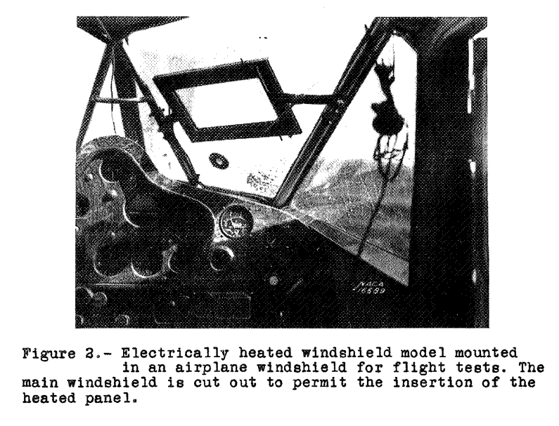
Electrically Heated Flight Model
The flight model of the electrically heated windshield was mounted in the right front windshield frame of a four-place cabin monoplane (fig. 2).
Air-Heated Flight Model
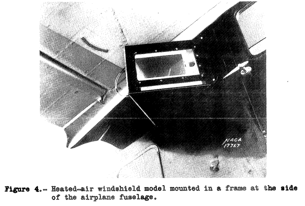
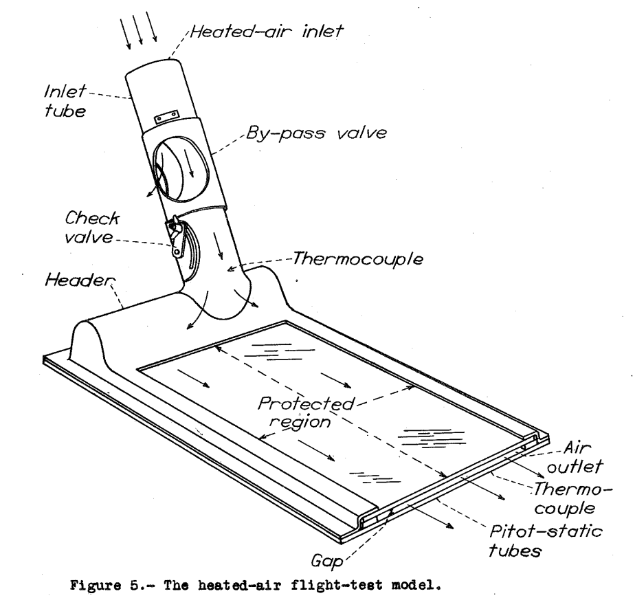
The heated-air windshield mounted on the airplane for flight tests is shown in figure 4. The test panel, when mounted as shown, was set into the side window of the cabin airplane at an angle of 30° with the side of the craft. This model was also mounted in a cut-out in the right front windshield during part of the tests, When mounted in the front windshield panel, the direction of the hot-air flow in the model with relation to the direction of the air stream over the outside was thought to be unfavorable to the most efficient operation of the heating system. In order to avoid the extensive changes required to both the airplane windshield frame and to the model to obtain a desirable orientation, the model was moved to the side location. The side mounting was therefore utilized for the rest of the tests because it eliminated the objectionable features of mounting in the front panel of this particular airplane and yet provided conditions that would give valid test results. The dimensions of the exterior of the frame were 9 by 14 inches. The size of the transparent region over which ice was prevented was 6 by 11 inch.
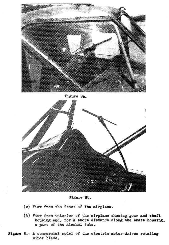
Rotating Windshield-Wiper Blades
Ice was prevented from forming by the rotating windshield-wiper blades but could not be removed if formation occurred before the blade was put in operation. Photographs showing the test panel after a flight during which ice was prevented from forming are shown in figures 12(a) and 12(b). All the alcohols used were satisfactory for the prevention of ice, although the denatured alcohol caused as light blurring of vision through the protected disk. No data are available regarding the contents of the denaturant used. Later tests were made with pure ethyl alcohol and with isopropyl alcohol. The quantity of alcohol used is thought to be correct. One gallon was sufficient for a flight of 2 hours in moderately severe icing conditions. Then ice was permitted to form prior to the rotation of the wiper blade shaft, ice could not be removed. Attempts to operate the rotating wiper blade after ice had formed on the glass resulted in mechanical failure of the drive.
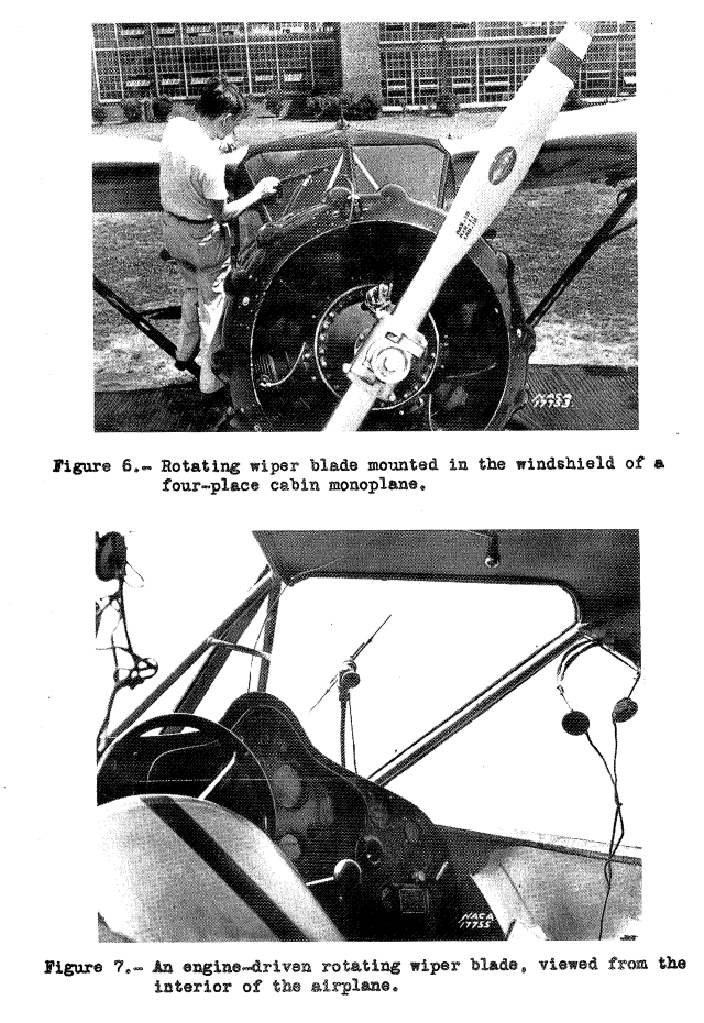
The person in the Figure 6 photo might be the author Lewis Rodert.
The heated-air panel appears to be the most satisfactory solution to the windshield-icing problem, provided that a source of air at a temperature of between 170 and 200 F is available. The air-heated panel has two advantages over the electrically heated panel; it is more easily designed and uses normally wasted exhaust-gas energy; whereas, the electrically heated panel must be kept liquid-tight and must use electric batteries for power. The air-heated model also has the same advantages over the windshield wiper with regard to the source of heat and, in addition, has the advantage of being free from moving mechanical parts. In as much as each of the systems tested has given, in some measure, satisfactory results, it is expected that all will find application according to the requirements and limitations of the particular installation. The possibility and advantages of combining the rotating wiper blade with the hot-air system will be noted. By such a combination, protection against ice will have been doubly provided over a limited area. In addition, the interior of the heated windshield will be protected against frost and provision will have been made for some vision through the windshield when flying in rain. The existing practice of making the airplane windshield retractable or removable by the pilot may become unnecessary if adequate protection against loss of vision due to rain or ice can be provided. The possibility is therefore noted that the added design complications resulting from the installation of ice-prevention equipment may in part be offset by other design simplifications.
CONCLUSIONS
Tests in the 7- by 3-foot ice tunnel and in flight indicated that:
1. Ice could be prevented from forming on the windshield by electric heat,by heated air, or by an alcohol-dispensing, rotating wiper blade. 2. Preformed ice could be removed from the airplane windshield by the use of either electric or hot-air heating. 3. The power required by a heating system for the protection against ice could be computed by one of the following equations:Pw = 7 * V ^0.78 watts per square foot
Pa = 24 * V ^0.78 B.T.U. per square foot per hourWhere Pw is the power required by heated wires;
Pa, the power required by heated air; and V, the airspeed in miles per hour.4.Approximately one-half gallon of alcohol per hour was required for the prevention of ice over a disk 10 inches in diameter covered by a rotating wiper blade during moderately severe icing conditions at air speeds up to 150 miles per hour.
NACA-TN-754 "Supersedes" NACA-SR-130, according to the nrts site, but "supersedes" is not noted on NACA-TN-754 nor NACA-SR-130. NACA-SR-130 and NACA-TN-754 have almost the same content, except that NACA-SR-130 adds the equations for heat loads and conclusions 3 and 4. I find this confusing, as NACA-TN-754 was published after NACA-SR-130 (although the sequence they were written or revised in may be different from the publishing dates). The images are better reproduced in the NACA-SR-130 download.
"A Method for Calculating the Heat Required for Windshield Thermal Ice Prevention Based on Extensive Flight Tests in Natural—Icing Conditions", NACA-TN-1434
This publication is extensive (102 pages). There are a lot a good images, so I will let the pictures tell most of the story.
SUMMARY
An equation is presented for calculating the heat flow required. from the surface of an internally heated windshield in order to prevent the formation of ice accretions during flight in specified. icing conditions. To ascertain the validity of the equation, comparison is made between calculated values of the heat required and measured values obtained for test windshields in actual flights in icing conditions.
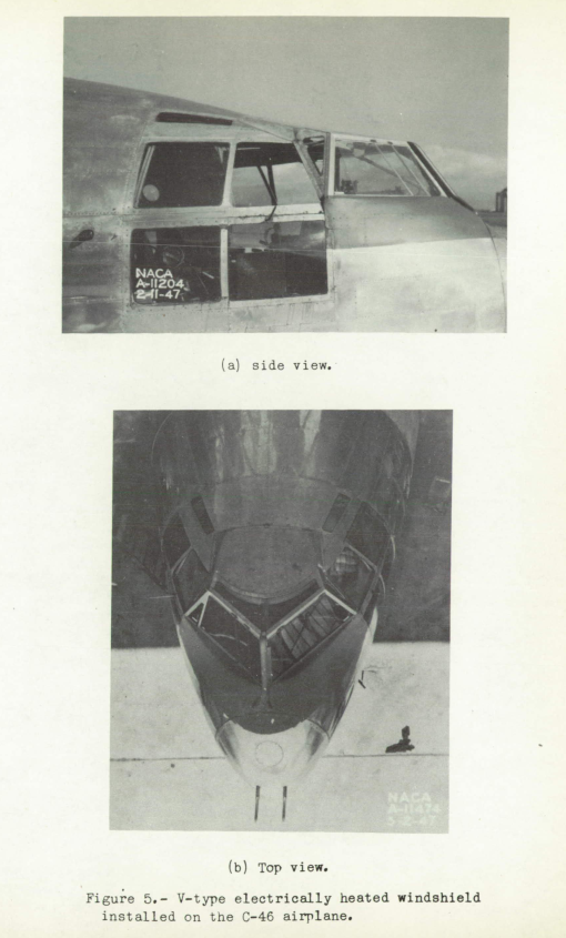
The test windshields were internally heated and provided data applicable to two common types of windshield configurations; namely the V-type and the type installed flush with the fuselage contours. These windshields were installed on a twin-engine cargo airplane and. the icing flights were conducted over a large area of the United States during the winters of 1945-46 and 1946-47. In addition to the internally heated windshield investigation, some test data were obtained for a windshield ice-prevention system in which heated air was discharged into the windshield boundary layer. The general conclusions resulting from this investigation are as follows:
1. The amount of heat required for the prevention of ice accretions on both flush- and V-type windshields during flight in specified. icing conditions can be calculated with a degree of accuracy suitable for design purposes.
2. A heat flow of 2000 to 2500 Btu per hour per square foot is required for complete and continuous protection of a V-type windshield in flight at speeds up to 300 miles per hour in a moderate cumulous [cumulus in current spelling] icing condition. For the same degree of protection and the same speed range, a value of 1000 Btu per hour per square foot suffices in a moderate stratus icing condition.
3. A heat supply of 1000 Btu per hour per square foot is adequate for a flush windshield located well aft of the fuselage stagnation region, at speeds up to 300 miles per hour, for flight in both stratus and moderate cumulous icing conditions.
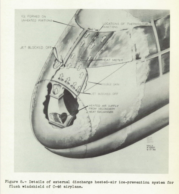
4. The external air discharge system of windshield thermal ice prevention is thermally inefficient and requires a heat supply approximately 20 times that required for an internal system having the same performance.
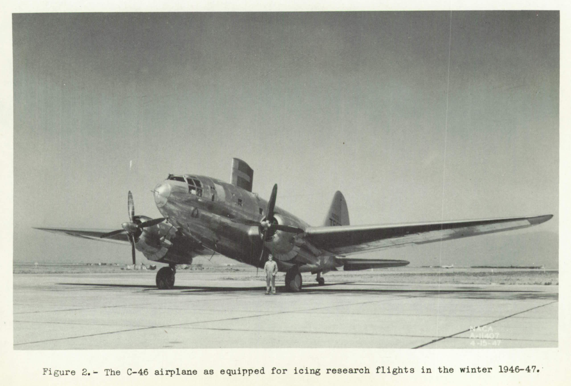
This is the C-46 configuration featured in the banner of the introduction to this website (colorized).
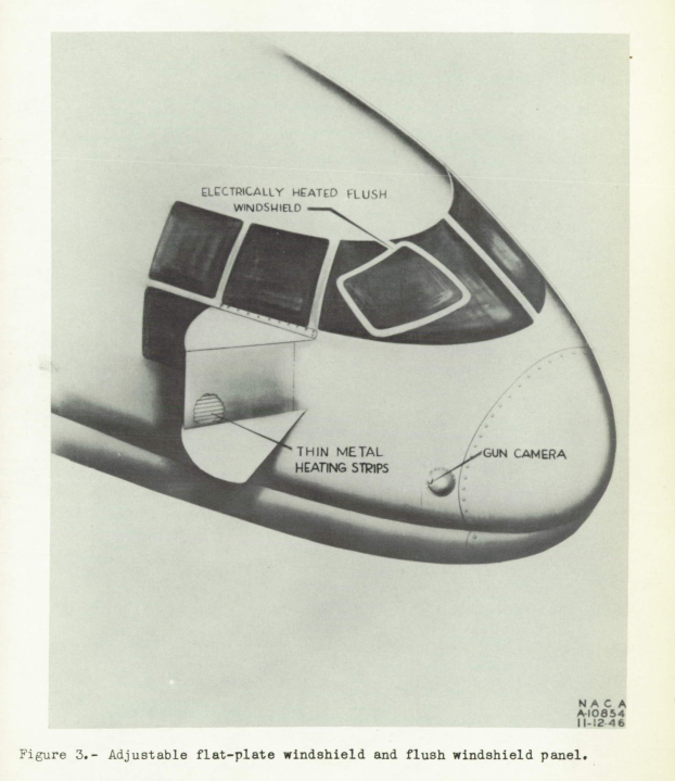
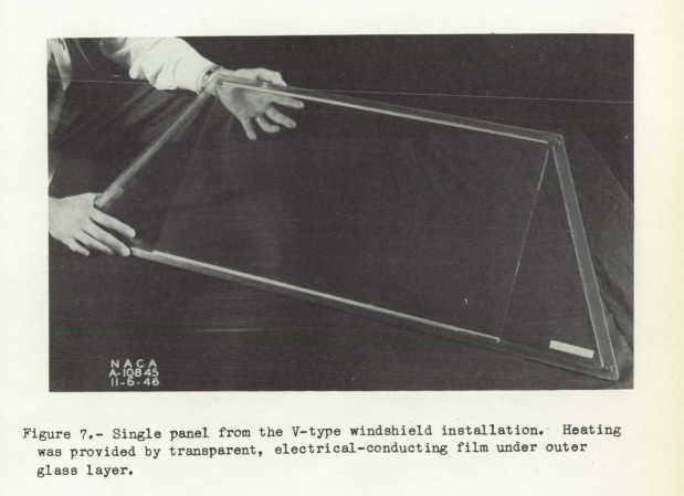
The transparent electrical-conducting film is the type of heating used on some current design heated windows (contrasting the earlier NACA-SR-130, where wires heated glycol between two window panes).
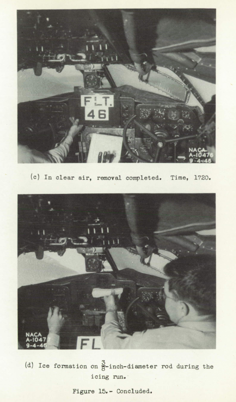
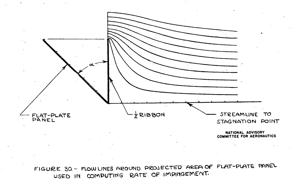
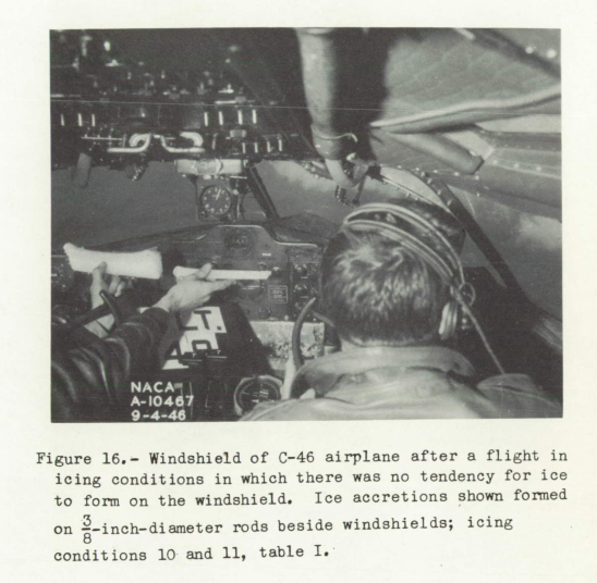
Considering first the case of the flat-plate panel, the assumption was made that the rate of water impingement on the panel would be equal to the rate of impingement on the projected area of the panel considered as one-half of a ribbon. (See fig. 30.) The efficiency of water impingement and the weight rate of water impingement w for various drop sizes have been computed for the three panel-angles at one flight condition and. are presented in table V. It is of interest to note that for drop diameters greater than 30 microns, as the panel angle is reduced (panel becoming more flush with the fuselage) the impingement efficiency is increased but the weight rate of water interception is decreased. Since this latter quantity is the item of greater significance from a heat-requirement standpoint, the desirability of low panel angles is evident. Optimum benefit of this advantageous feature would be expected. to occur with flush windshield installations. The flush windshield: in the C-46 airplane during the 1945-46 winter provided confirmation in this respect, since windshield icing was encountered in only 8 out of 30 actual flights in icing clouds. Figure 16 shows the lack of ice accretions on the flush windshield after a flight in a cloud which produced the accretions shown on 3/8-inch rods located just below the pilot's and copilot's windshields.
To obtain an estimation of M the rate of water impingement on the flush windshield for specific design conditions, the assumption was made that the impingement would be the same as that on a portion of a sphere having a diameter equal to the fuselage maximum diameter. (See fig. 31.) The manner in which the water-drop trajectory calculation method for a sphere presented in reference 4 was applied to the configuration shown in figure 31 is discussed in detail in Appendix A of this report. The calculated rate of water impingement on the flush test panel, based on the procedure discussed in Appendix A, is presented in table VI for various drop-size diameters. The same flight conditions employed for the flat-plate water interception calculations (table V) were again assumed to apply.
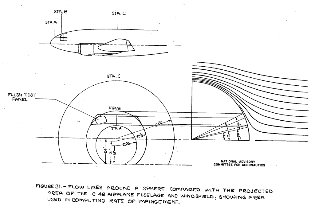
Reference 4 is Langmuir and Blodgett 4, which we have seen much of before in the Icing on cylinders thread and elsewhere. While the airplane body and windows to a perpendicular ribbon or sphere analogy might seem a little strained, it was the level of analysis readily available at the time (and the ribbon analysis used for the flat panel windshield gets perpetuated in ADS-4, published more than a decade later). Such an analysis shows a low rate of small, cloud water drop impingement on the windshield. In Table IV, 20 micrometer diameter drops are predicted to not impinge at all, while 30 micrometer diameter drops do impinge.
Rain sized drops have a more appreciable rate of impingement. Freezing rain is a challenge for many types of ice protection systems, including windshield heating.
See also
- Kushnick, Jerome L.: Thermodynamic Design of Double-Panel, Air-Heated Windshields for Ice Prevention, NACA-RB-3F24, 1943 (also published as NACA-WR-A-56). ntrs.nasa.gov
This has more details on calculations for air-heated windshields.
- Ruggeri, Robert S.: Preliminary Data on Rain Deflection from Aircraft Windshields by Means of High Velocity Jet-Air Blast. NACA-RM-E55E17a, July 25, 1955. ntrs.nasa.gov
> review: NACA-RM-E55E17a
Not specifically about icing, but this has some similarities to the external discharge system of NACA-TN-1434.
- Bowden, D.T, et.al., “Engineering Summary of Airframe Icing Technical Data”, FAA Technical Report ADS-4, General Dynamics/Convair, San Diego, California, 1964. apps.dtic.mil
In the thermodynamics thread we previously reviewed ADS-4.
This has more details on windshield ice protection, including freezing point depressant fluids.
Conclusions
In brief time, 1939 to 1947, windshield ice protection matured rapidly. The problem was driven by "urgent need", and NACA and the aviation industry responded.
There are at least three viable technology options available for aircraft today (electric heating, heated air, and fluids).
(By "viable" I mean that there is documentation on how to design the system. We will see examples in the upcoming Design Manuals post.)
Citations
An online search (scholar.google.com) found citations for
NACA-SR-130 6 times, and
NACA-TN-1434 8 times.
Notes
-
Rodert, Lewis A.: "An Investigation of the Prevention of Ice on the Airplane Windshield", NACA-SR-130, 1939. ntrs.nasa.gov. ↩
-
Rodert, Lewis A.: "An Investigation of the Prevention of Ice on the Airplane Windshield", NACA-TN-754, 1940. ntrs.nasa.gov. ↩
-
Jones, Alun R., Holdaway, George H., and Steinmetz, Charles P.: A Method for Calculating the Heat Required for Windshield Thermal Ice Prevention Based on Extensive Flight Tests in Natural—Icing Conditions. NACA-TN-1434, 1947. ntrs.nasa.gov ↩
-
Langmuir, Irving, and Blodgett, Katherine B.: A Mathematical Investigation of Water Droplet Trajectories. Tech. Rep. No. 5418, Air Materiel Command, AAF, Feb. 19, 1946. (Contract No. W-33-038-ac-9151 with General Electric Co.) ↩