"... it was not surprising that scale ice shapes were again a good match for the reference"
NASA/CR-2004-212875 1
Summary
Similarity calculations for ice shapes are detailed.
Key Points
- Several scaling methods with differing parameters are compared in tests.
- "The Ruff method, supplemented with the constant-WeL approach to calculate scale velocity, is recommended"
- Examples are included of how to deal with limitations (temperature, lwc, etc.)
Abstract
This manual reviews the derivation of the similitude relationships believed to be important to ice accretion and examines ice-accretion data to evaluate their importance. Both size scaling and test-condition scaling methods employing the resulting similarity parameters are described, and experimental icing tests performed to evaluate scaling methods are reviewed with results. The material included applies primarily to unprotected, unswept geometries, but some discussion of how to approach other situations is included as well. The studies given here and scaling methods considered are applicable only to Appendix-C icing conditions. Nearly all of the experimental results presented have been obtained in sea-level tunnels. Recommendations are given regarding which scaling methods to use for both size scaling and test-condition scaling, and icing test results are described to support those recommendations. Facility limitations and size-scaling restrictions are discussed. Finally, appendices summarize the air, water and ice properties used in NASA scaling studies, give expressions for each of the similarity parameters used and provide sample calculations for the size-scaling and test-condition scaling methods advocated.
Discussion
I consider this to be "The" reference for scaling test conditions for ice shapes in areas without ice protection.
This is a lengthy publication (78 pages, 32 figures), with much high quality technical content, so this review will be highly condensed.
There is a detailed discussion of potential scaling parameters, and reviews of test data that show which ones may have importance. Several we have seen before in the Icing Wind Tunnel Test Thread.
3.8. Summary of Potential Scaling Parameters
For convenience, all the similarity parameters discussed above that appear to have the most influence on ice accretion and are therefore most likely to form the basis of a scaling method will be listed here again. All are dimensionless except for the water-energy and air-energy transfer terms (φ and θ) which have dimensions of temperature.
- Reynolds number, Rea (eq. (3.1))
- Modified inertia parameter, Ko (eq. (3.8))
- Stagnation collection efficiency, βo (eq. (3.13))
- Accumulation parameter, Ac (eq. (3.26) - Relative heat factor, b (eq. (3.55))
- Water-energy transfer parameter, φ (eq. (3.56))
- Air-energy transfer parameter, θ (eq. (3.57))
- Freezing fraction, no (eq. (3.59))
- Weber number, for example: Wec, WeL, Weδ, Weh, Wew or Wet (eqs. (3.66) (3.69), (3.70), (3.72), (3.79) or (3.80))
- Water film thickness, hfilm/d, (eq. (3.74))Note that in place of the modified inertia parameter, Ko, the collection efficiency at the leading edge, βo, can be used. βo is a more sensitive parameter than Ko. These two parameters are directly related by equation (3.13).
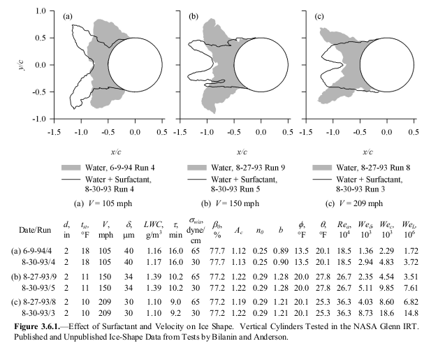
Tests with a surfactant added to the water spray showed a notable effect of changing the surface tension, indicating an importance to the Weber number.
Several potential scaling methods were considered:
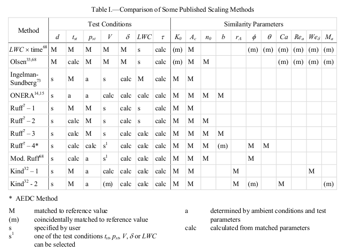
Figure 5.3.4 graphs some of the information in Table V along with additional data. Here, the scale-to-reference velocity ratio is given as a function of the reference-to-scale size ratio for a range of size ratios from 1.7 to 4. The shaded band represents scale velocity ratios in the range of ±15%. The velocity ratio for most of the methods was calculated for a reference velocity of 150 mph. At this reference velocity, however, the routines used to calculate scale velocity failed for the average-velocity and constant-Wek methods at scale ratios greater than 2; therefore, to obtain values over the complete range of scale ratios, the reference velocity used for these methods was 115 mph. It is evident that even with a scale ratio as high as 4 there are a number of methods whose scale velocities differ by no more than ±15%. This is not a sufficient difference to produce significant variations in ice shape.
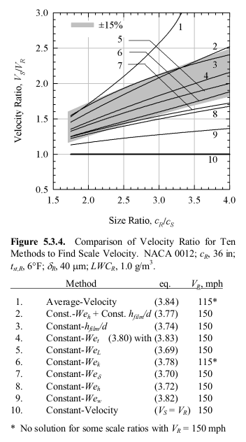
As Table V and figure 5.3.4 show, for half-size scaling, the scale velocity resulting from matching WeL falls in the range between constant Weδ and average V that has shown reasonable scaling results in past studies. At this time, WeL seems to have greater experimental justification than other similarity parameters. The practical advantage of using constant WeL is that the scale velocity-to-reference velocity ratio is simply the square root of the size ratio (eq. (3.71)). Furthermore, it leads to a more moderate scale velocity than some of the similarity parameters that might be used.
Conclusions
Geometric scaling
5.3.7. Recommended Method to Scale Size
The Ruff method reviewed in section 5.3.3, supplemented with the constant-WeL approach (section 5.3.4) to calculate scale velocity, is recommended for simulating the main ice shape with a model scaled in size. This method requires matching scale and reference model non-dimensional geometry and AOA, as well as scale and reference values of the similarity parameters Ko, Ac, no, φ, θ and WeL for tunnels with altitude capability or Ko, Ac, no, WeL and the choice of either φ or θ for sea-level tunnels. At this time, matching of WeL appears to have the strongest analytical basis for finding scale velocity. The velocity resulting from use of this method is of the same magnitude as several other proposed approaches listed in Table V, and experimental evaluation of this method seems to validate it. As greater understanding of water-film effects is gained, this recommendation may change.
Scale drop size can be found either from equation (3.18) or by matching Ko from equation (3.8). For simulating the main ice shape, a great deal of flexibility is possible in choosing scale drop size, because, as shown in figures 3.3.6 and 3.3.7, for the conditions investigated to date, Ko has no measurable effect on main ice shape. Nevertheless, it is recommended that Ko be matched whenever possible, because it does affect the impingement limit. If scale and reference Kocan not be matched, instead of simply matching Ac, the product βoAc should be matched as closely as possible. Furthermore, if Ko is not matched and impingement limits are important additional tests should be performed at the reference βo, Ac and no to determine these limits. For scaled impingement-limit tests, the parameters φ (or θ) and WeL, necessary for faithful scaling of main ice shapes, can be ignored.
For scaling tests to determine main ice shape, there is a high probability that the parameters φ and θ do not have to be matched to the reference values, but additional testing is required to confirm that this simplification is valid. Until such testing is completed, it is recommended that these parameters continue to be used.
The matching of all the parameters required to find scale test conditions necessitates solving several equations simultaneously. The programming of solutions to this system of equations is not difficult, and is simplified by the use of mathematical software such as Mathcad® or Mathematica®.
The "Ruff method, supplemented with the constant-WeL approach" is detailed in Appendix B with example calculations.
Dealing with limitations
Often, the theoretical ideal test condition is not achievable, due to facility or test article limitations. Some guidance is provided.
Velocities are limited by physical constraints, as well.
Large test articles may be velocity limiting. In some cases, the drag is large so that the fan power can only achieve something below the nominal test section maximum velocity. In other cases, the test article may be load limited to some airspeed below the nominal test section maximum velocity.
In some cases, the scale total temperature found by matching either φ or θ is above freezing. References 35 and 46 showed that when total temperatures exceeded 27°F (-3°C) ice shapes are distorted enough that a good match of the reference is not possible. Thus, when scale total temperature is greater than 27°F, φ and θ must be abandoned and a scale temperature selected such that the total temperature is below 27°F (-3°C). LWC must then also be adjusted to maintain constant no.
It is not clear if this is a characteristic specific to the NASA Glenn IRT, or if it is a general result.
Appendix B has an example of dealing with a temperature limitation.
For very short accretion times for which ice features do not have time to form, simplifications to the above recommendations are possible. For example, a constant-velocity approach can be substituted for constant-WeL, as discussed in section 5.3.5. For short times (small values of Ac) the primary concern should be to match scale and reference βoAc.
Appendix B also has an example of adjusting at test condition where the ideal condition is outside the capabilities of the spray nozzles.
While NASA/CR-2004-212875 did not specifically recommend it, I recommend using the "Ruff method, supplemented with the constant-WeL approach" for Appendix C icing cases, regardless of whether the test article is geometrically scaled.
Acceptable Parameter Variations and The effects of tolerances
5.3.6. Acceptable Parameter Variations
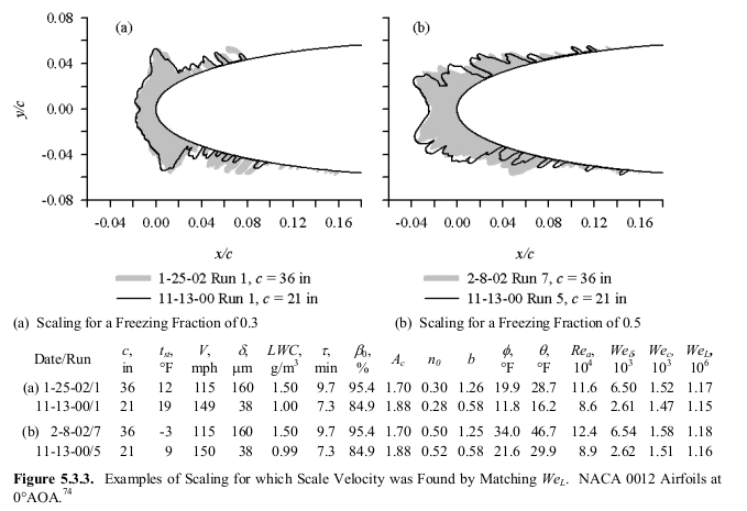
Even for glaze ice, the similarity parameters may not always need to be matched precisely between scale and reference to insure good scale ice shapes. In fact, in practice, uncertainties in test conditions make it impossible to specify precisely the scale parameter values. Thus, it is helpful to know what tolerances are acceptable. This topic was reviewed in reference 19. There it was recommended that uncertainties in test parameters should be minimized such that the scale-reference match of no and of Ac should be within ±10%. If scale and reference βo do not match, the product βoAc should match within ±10%. Ice shape is not as sensitive to changes in velocity as to those in no and Ac, as shown in section 5.3.4. It is recommended, however, that WeL,S, the similarity parameter from which scale velocity is found, be maintained within ±15% of WeL,R. Additional testing of the effects of variations in this parameter on ice shape is needed to better establish acceptable variations in WeL.A variation of the modified Ruff method [ref. 46] for sea-level tunnels is to determine scale temperature by matching θ while ignoring φ. This approach results typically in lower temperatures than by using constant φ. Reference 46 concluded from limited testing that it made no difference to the ice shape whether temperature was found by matching φ or θ. Reference 49 also showed scale ice shapes that matched the reference when temperature was found by applying constant θ with φ unmatched. These results are not surprising since neither φ nor θ has been shown to have an effect on ice shape independent of the freezing fraction. Thus, it is highly probable that the scale temperature (or, alternatively, LWC) can be chosen arbitrarily with the LWC (or temperature) determined by matching scale and reference no. Anderson and Tsao [ref. 74] demonstrated good matches of scale and reference shapes for conditions for which neither φ nor θ matched reference values [emphasis added]. Additional testing is needed to confirm this result, but if validated, it would provide useful flexibility in the definition of scale test conditions.
Here is the apparent priorities for scaling parameter matching, and the recommended tolerances, summarized from above (highest priority first).
- product of βo Ac +/-10%
- no +/-10%
- WeL +/-15%
- βo (no specific tolerance)
- φ (no specific tolerance)
- Other parameters (Mach, θ, other Weber numbers, etc.) may not be important.
The tolerances above are for reference to scale comparison. However, in an icing wind tunnel control values are only known to a certain tolerance, and can vary during a test.
Note from above (emphasis added):
In fact, in practice, uncertainties in test conditions make it impossible to specify precisely the scale parameter values.
Here is a simplified version of "Table 1 Test Section Performance Targets" from SAE ARP5905 2 for comparision:
| Tunnel Control Parameter | Measurement Uncertainty | Tunnel Centerline Temporal Stability |
|---|---|---|
| Airspeed | +/-1% | +/-2% |
| Static Temperature, C | +/-0.5 | +/-0.5 |
| LWC | +/-10% | +/-20% |
| MVD | +/-10% | +/-10% |
While the "temporal stability" value for LWC may appear to be large, natural icing clouds typically have similar if not larger variations over small scales (seconds in flight). Here is an example from FAA-RD-80-24 3 (note the LWC plot):
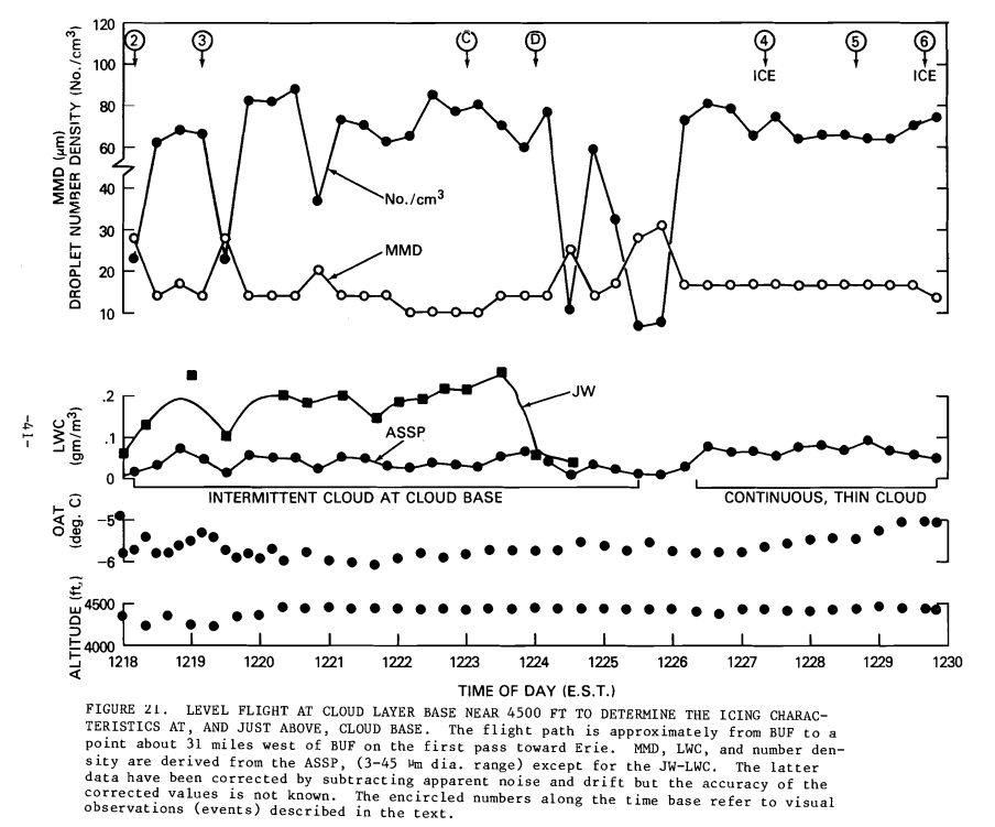
Figure 21 of FAA-RD-20-24
The measurement uncertainty value for LWC, however, is comparable to the recommended tolerance on no, and the product of βoAc. However, if all values are known when determining a test point, the product of βoAc can be set by adjusting icing time.
The effect of MVD differences on βo is non-linear, and depends on the specific condition.
So, what ends up being tested may be different from the planned, ideal similarity condition.
Recommended Future Studies in Scaling
This manual concentrated on scaling for simple geometries and two-dimensional wing sections. Future studies need to address such applications as swept wings, rotor-craft and scaling for ice-protection systems. For small sweep angles, swept-wing accretions may be close enough to unswept that the scaling methods in this manual might be applicable. Testing is required to verify this approach, however, and to date none has been done.
I find the recommendations for thermal systems to be rather incomplete:
Scaling for thermal ice-protection systems will require the addition of terms to the energy balance equation of section 3.5 to represent the ice-protection system. For such applications of scaling, there is no ice shape to be concerned about, so, in addition to thermal similarity parameters, it is only necessary to match the product βoAc to insure the correct water catch is simulated. This is not difficult to do, but scaling methods for thermal ice protection need to be evaluated.
We will look at this more in a future post, "Anti-Ice Test Similarity".
Citations
NASA/CR-2004-212875 cites 78 references (too numerous to list here).
I will point out four from the NACA-era:
- 1. von Glahn, Uwe H., “Use of Truncated Flapped Airfoils for Impingement and Icing Tests of Full-Scale Leading-Edge Sections,” NACA-RM-E56E11, July 1956.
- 8. Langmuir, Irving and Blodgett, Katharine B., “A Mathematical Investigation of Water Droplet Trajectories,” Army Air Forces Technical Report No. 5418, February 1946.
- 21. Messinger, B.L., “Equilibrium Temperature of an Unheated Icing Surface as a Function of Airspeed,” J. Aeron. Sci. vol. 20 no. 1, January 1953, pp 29-42.
- 25. Gelder, Thomas F. and Lewis, James P., “Comparison of Heat Transfer from Airfoil in Natural and Simulated Icing Conditions,” NACA-TN-2480, September 1951.
And three we saw before in the Icing Wind Tunnel Test Thread:
- 7. Ruff, G.A., “Analysis and Verification of the Icing Scaling Equations,” AEDC-TR-85-30, Vol 1 (Rev), March 1986.
- 39. Bilanin, A. J., “Proposed Modifications to the Ice Accretion/Icing Scaling Theory,” AIAA-88-0203, January 1988.
- 69. Bartlett, C. Scott, “An Empirical Look at Tolerances in Setting Icing Test Conditions with Particular Application to Icing Similitude,” DOT/FAA.CT-87/31 and AEDC-TR-87-23, August 1988.
An online search 4 found 10 citations of "Manual of Scaling Methods".
Notes
-
Anderson, David N.: Manual of scaling methods. No. E-14272, NASA/CR-2004-212875. 2004. ntrs.nasa.gov ↩
-
Aerospace, S. A. E. "SAE ARP 5905 Calibration and acceptance of icing wind tunnels." ARP5905 ↩
-
Jeck, Richard K: "Icing Characteristics of Low Altitude, Supercooled Layer Clouds", FAA-RD-80-24, May, 1980. apps.dtic.mil ↩