"If the values of the K and φ parameters for the model and full-scale nacelle are maintained the same, the icing characteristics of the model will be similar to the icing characteristics of the full-scale"
Summary
Early examples of icing test scaling are noted.
Key Points
- Three publication that mention scaling are reviewed.
- Some challenges with scaling are noted.
- A airfoil design of a full scale leading edge truncated with an aft flap addresses some challenges.
Discussion
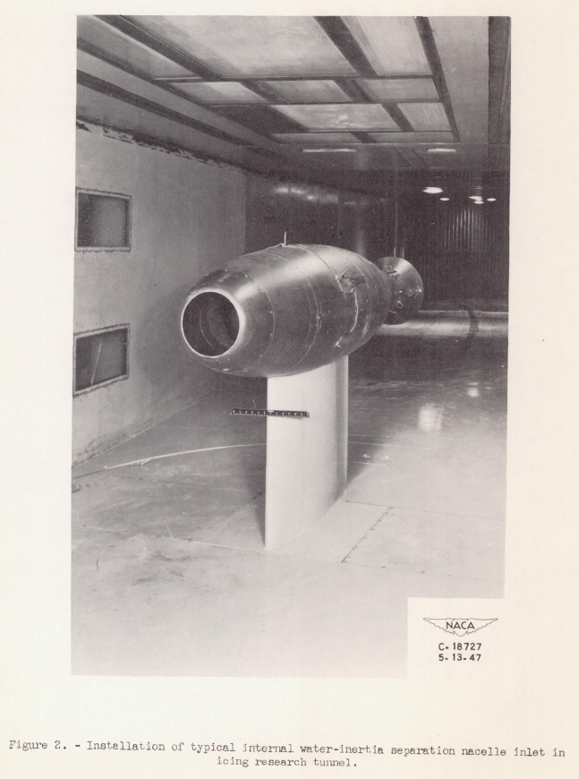
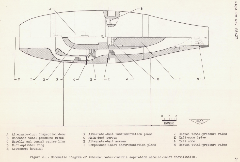
NACA-RM-E8A27 "Ice Protection of Turbojet Engines by Inertia Separation of Water, I - Alternate-Duct System" 1
This is the earliest example that I have found of using dimensionless water drop impingement terms for test similarity calculations.
The results of a preliminary investigation of internal water- inertia separation inlets designed to prevent automatically the entrance of large quantities of water into a turbojet engine in icing conditions are presented. A simplified analytical approach to the design of internal water-inertia separation inlets is included. The analysis is applied specifically to the model investigated.
The results show that to be effective in separating the free water from the air stream in order to prevent screen and stator-blade icing, an inlet of this type had a 75-percent ram-pressure recovery at the design inlet-velocity ratio in an icing condition. For normal nonicing operation, the ram-pressure recovery is comparable to a direct-ram installation The ram-pressure recovery and the circumferential uniformity of the mass flow in the inlets was relatively independent of angle of attack.
Extrapolation of model icing investigations to full scale.
If the values of the K and φ parameters (where K = f( a^2 V / C) and φ = f( ρ^2 V C)) for the model and full-scale nacelle are maintained the same, the icing characteristics of the model will be similar to the icing characteristics of the full-scale nacelle as determined by Langmuir and Blodgett. Each component of a complicated duct system will have its own K and φ values; however by choosing the most important component for a particular investigation a satisfactory extrapolation to full scale can be attained. The calculations of K and φ contain four important variables: velocity, drop diameter, body dimension, and density, which can be varied simultaneously, separately, or in combination. For the investigation presented, the data were extrapolated from half scale to full scale by holding K constant and so changing the density or pressure altitude for the full-scale nacelle that φm for the half-scale model was the same as φf The half-scale model conditions for these investigations thus pertain to full-scale conditions at a pressure altitude of approximately 21,000 feet.
where a is water drop diameter
      V is air speed
      C is chord length
      ρ is air density
      μ is air viscosity
Using an analogy such as Re = ρVC/μ, a subscale test value of C may be compensated for by increasing ρ or V (or in combination) to maintain a full scale flight Re value. Facilities such as the Variable-Density Wind Tunnel (see NACA-TR-446) can be pressurized to achieve a high density. Here, the water drop impingement dimensionless terms K and φ are used.
The dimensionless terms K and φ that describe water drop impingement come from Langmuir and Blodgett 2, but Langmuir and Blodgett were not included in the references of NACA-RM-E8A27.
The IRT is not pressurized, so the test section pressure will be close to sea level pressure. Thus, a test with a half scale test article in a close to sea level pressure facility is related full scale flight at altitude.
The example does not detail all of the four key variables for the flight and test cases required to maintain the same K = f( a^2 V / C) and φ = f( ρ^2 V C) values. At 21,000 ft. the air density is about 0.5 that of sea level (if using a standard atmosphere table, the density would be less if temperature was held constant). Here are relative values that maintain the K and φ values. There is more than one flight set that corresponds to the test values.
| Relative Value | a | V | Chord | ρ | a^2 V / C | ρ^2 V C |
|---|---|---|---|---|---|---|
| Test | 1 | 1 | 0.5 | 1 | 2 | 0.5 |
| Flight 1 | 1 | 2 | 1 | 0.5 | 2 | 0.5 |
| Flight 2 | 1.41 | 1 | 1 | 0.707 | 2 | 0.5 |
The first flight set appears to be what was described in the example, but the flight velocity being twice the test value was not mentioned. The second flight set scales drop size, but uses the same velocity as the test. The K = f( a^2 V / C) = 2 value cannot be achieved with a, V, and C all being 1.
This illustrates a challenge of scaling: scaling one dimensional parameter often requires scaling at least one other dimensional parameter (sometimes several) to keep a dimensionless parameter value constant.
NACA-RM-E50E03, "Investigation of Aerodynamic and Icing Characteristics of Water-Inertia-Separation Inlets for Turbojet Engines" 3
This considers testing a subscale model at sea level pressure and comparing that to flight.
SUMMARY The results of an investigation of several internal water- inertia-separation inlets consisting of a main duct and an alternate duct designed to prevent automatically the entrance of large quantities of water into a turbojet engine in icing conditions are presented. Total-pressure losses and icing characteristics for a direct-ram inlet and the inertia-separation inlets are compared at similar aerodynamic and simulated icing conditions. Complete ice protection for inlet guide vanes could not be achieved with the inertia-separation inlets investigated. Approximately 8 percent of the volume of water entering the nacelles remained. In the air passing into the compressor inlet, heavy alternate-duct-elbow ice formations caused by secondary inertia separation resulted in rapid total-pressure losses and decreases in mass flow. The duration in an icing condition for an inertia-separation inlet, without local surface heating, was increased approximately four times above that for a direct-ram inlet with a compressor-inlet screen. For normal nonicing operation, the inertia-separation-inlet total-pressure losses were comparable to a direct-ram installation. The pressure losses and the circumferential uniformity of the mass flow in all the inlets were relatively independent of angle of attack. Use of an inertia-separation inlet would in most cases require a larger diameter nacelle than a direct-ram inlet in order to obtain an alternate duct sufficiently large to pass the required engine air flow at duct Mach numbers below 1.0 at the minimum area.
For full-scale considerations, the alternate-duct area must therefore be increased to an extent that it would pass sufficient air to the engine at a reasonable Mach number and pressure loss. This design requirement could be attained with configuration E by increasing the inlet gap about 26 percent and then scaling the entire configuration to fit the engine. An increase in the inlet gap, however, does not appear to be feasible for good water separation.
The test demonstrated the feasibility of water separation inlet design, but the specific design tested does not appear to be feasible for flight.
This illustrates another challenge of scaling and test in a ground level, limited Mach range facility.
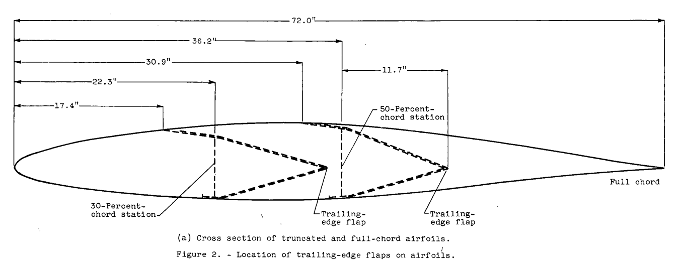
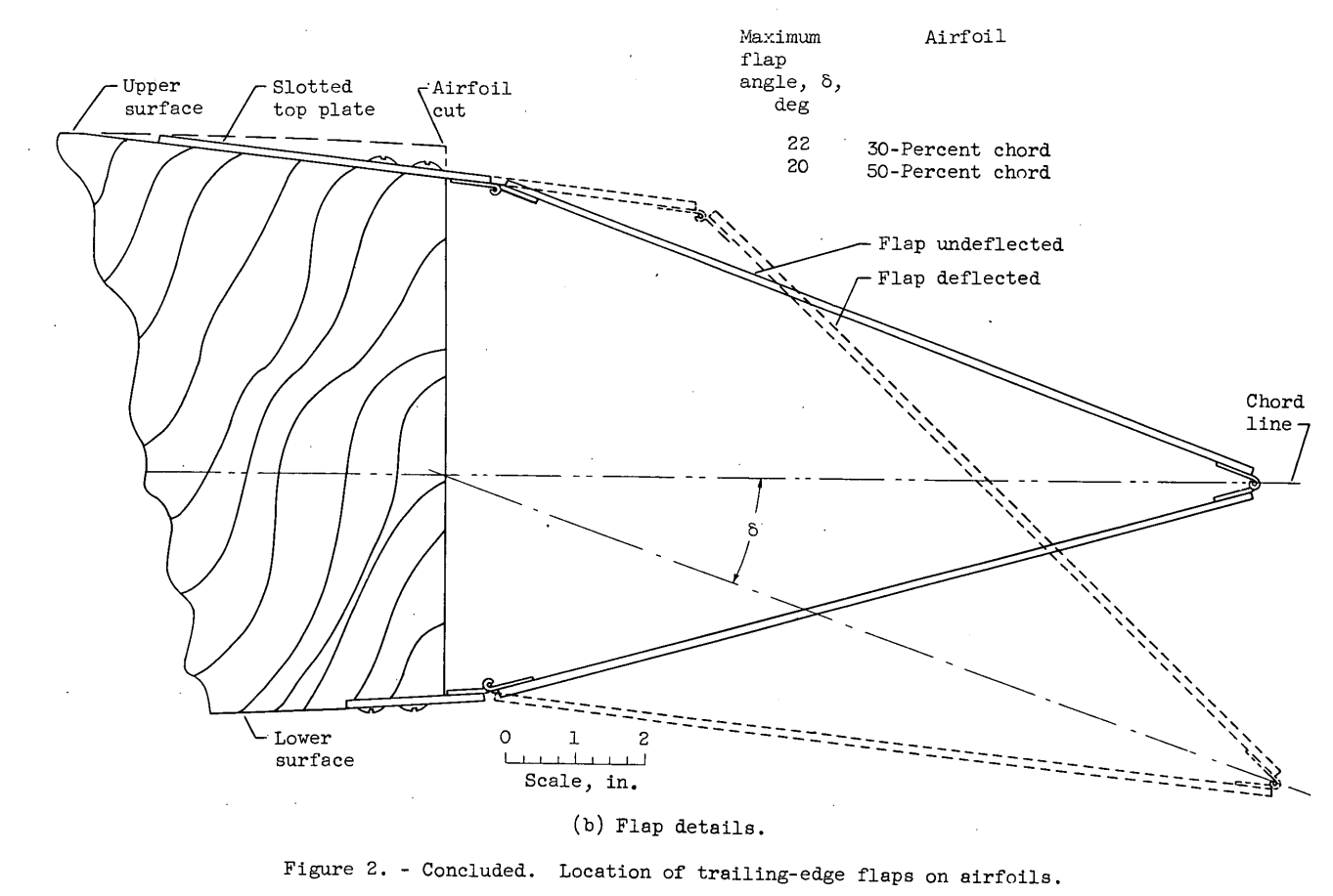
NACA-RM-E56E11, "Use of Truncated Flapped Airfoils for Impingement and Icing Tests of Full-Scale Leading-Edge Sections" 4
The use of truncated airfoils is described. Keeping a full scale leading edge avoids geometric scaling in test similarity calculations, but allows smaller test articles to keep within the physical limits of the test facility.
In an effort to increase the operational range of existing small icing tunnels, the use of truncated airfoil sections has been suggested. With truncated airfoils, large-scale or even full-scale wing-icing- protection systems could be evaluated. Therefore, experimental studies were conducted in the NACA Lewis laboratory icing tunnel with an NACA 651-212 airfoil section to determine the effect of truncating the airfoil chord on velocity distribution and impingement characteristics. A 6-foot-chord airfoil was cut successively at the 50- and 30-percent-chord stations to produce the truncated airfoil sections, which were equipped with trailing-edge flaps that were used to alter the flow field about the truncated sections. The study was conducted at geometric angles of attack of 0° and 4°, an airspeed of about 156 knots, and volume-median droplet sizes of 11.5 and 18.6 microns. A dye-tracer technique was used in the impingement studies.
With the trailing-edge flap on the truncated airfoil deflected so that the local velocity distribution in the impingement region was substantially the same as that for the full-chord airfoil, the local impingement rates and the limits of impingement for the truncated and full-chord airfoils were the same. In general, truncating the airfoils with flaps undeflected resulted in a substantially altered velocity distribution and local impingement rates compared with those of the full-chord airfoil. The use of flapped truncated airfoils may permit impingement and icing studies to be conducted with full-scale leading-edge sections, ranging in size from tip to root sections.
This technique has been refined and is still used today 5.
Citations
NACA-RM-E8A27 cites 4 publications:
- von Glahn, Uwe H., and Renner, Clark E.: Development of a Protected Air Scoop for the Reduction of Induction-System Icing. NACA-TN-1134, 1946. ntrs.nasa.gov
- Baals, Donald D., Smith, Norman F., and Wright, John B.: The Development and Application of High-Critical-Speed Nose Inlets. NACA-ACR-L5F30a, 1945. ntrs.nasa.gov
- Cohen, Herbert N.: Investigation of Intake Ducts for a High-Speed Subsonic Jet-Propelled Airplane. NACA-RM-L7C24a, 1947. apps.dtic.mil
- Stickley, A. R.: Some Remarks on the Physical Aspects of the Aircraft Icing Problem. Jour. Aero. Sci., Vol. 5, no. 11, Sept. 1938, pp. 442-446.
NACA-RM-E50E03 cites 6 publications:
- von Glahn, Uwe H.: Ice Protection of Turbojet Engines by Inertia Separation of Water, I - Alternate-Duct System. NACA-RM-E8A27, 1948. ntrs.nasa.gov
- Callaghan, Edmund E., Ruggeri, Robert S., and Krebs, Richard P.: Experimental Investigation of the Hot-Gas Bleedback for Ice Protection of Turbojet Engines, I - Nacelle with Offset Air Inlet. NACA-RM-E8D13, 1948. ntrs.nasa.gov
- Naumann: Wlrkungsgrad von Diffusoren bel hohen Unterechallgeschwindigkeiten. PB Nr. 1705, ZWB (Berlin-Adlershof), Dez. 18, 1942.
- Langmuir, Irving, and Blodgett, Katherine B.: A Mathematical Investigation of Water Droplet Trajectories. Tech. Rep. No. 5418, Air Materiel Command, AAF, Feb. 19, 1946. (Contract No. W-33-038-ac-9151 with General Electric Co.)
- Sanders, Newell D., and Behun, Michael: Generalization of Turbojet- Engine Performance in Terms of Pumping Characteristics. NACA-TN-1927, 1949. ntrs.nasa.gov
- Acker, Loren W.: Preliminary Results of Natural Icing of an Axial-Flow Turbojet Engine. NACA-RM-E8C18, 1948. ntrs.nasa.gov
NACA-RM-E56E11 cites 5 publications:
- Hauger, H. H., and Englar, K. G.: Analysis of Model Testing in an Icing Wind Tunnel. Rep. No. SM 14993, Douglas Aircraft Co., Inc., May 14, 1954.
- Sibley, P. J., and Smith, R. E., Jr.: Model Testing in an Icing Wind Tunnel. Rep. No. LR 10981, Lockheed Aircraft Cor., Oct. 14, 1955.
-
von Glahn, Uwe H., Gelder, Thomas F., and Smyers, William H., Jr.: A Dye-Tracer Technique for Experimentally Obtaining Impingement Characteristics of Arbitrary Bodies and a Method for Determining Droplet Size Distribution. NACA-TN-3338, 1955. ntrs.nasa.gov
-
Langmuir, Irving, and Blodgett, Katherine B.: A Mathematical Investigation of Water Droplet Trajectories. Tech. Rep. No. 5418, Air Materiel Command, AAF, Feb. 19, 1946. (Contract No. W-33-038-ac-9151 with General Electric Co.)
- Abbott, Ira H., von Doenhoff, Albert E., and Stivers, Louis S., Jr.: Summary of Airfoil Data. NACA-TR-824, Mar. 1945. ntrs.nasa.gov
Notes
-
von Glahn, Uwe H.: Ice Protection of Turbojet Engines by Inertia Separation of Water, I - Alternate-Duct System. NACA-RM-E8A27, 1948. ntrs.nasa.gov ↩
-
Langmuir, Irving, and Blodgett, Katherine B.: A Mathematical Investigation of Water Droplet Trajectories. Tech. Rep. No. 5418, Air Materiel Command, AAF, Feb. 19, 1946. (Contract No. W-33-038-ac-9151 with General Electric Co.) books.google.com ↩
-
von Glahn, Uwe H., and Blatz, Robert E.: Investigation of Aerodynamic and Icing Characteristics of Water-Inertia-Separation Inlets for Turbojet Engines. NACA-RM-E50E03, 1950. ntrs.nasa.gov ↩
-
von Glahn, Uwe H.: Use of Truncated Flapped Airfoils for Impingement and Icing Tests of Full-Scale Leading-Edge Sections. NACA-RM-E56E11, 1956. ntrs.nasa.gov ↩
-
Fujiwara, Gustavo EC, et al. "A hybrid airfoil design method for icing wind tunnel tests." 5th AIAA atmospheric and space environments conference. 2013. available at icing.ae.illinois.edu ↩