"drag coefficient (Cd) was used as an index of similitude by quantitatively indicating how much the shape or ice surface changed"
"An Empirical Look at Tolerances in Setting Icing Test Conditions with Particular Application to Icing Similitude" 1
Summary
An investigation into which icing conditions parameters affect icing similtiude as measured by aerodynamic drag effects.
Abstract
Often, engine icing tests cannot be conducted at conditions that are considered the critical test points because of aircraft engine test facility operational constraints or the inability to find the desired conditions in natural icing flight tests. The use of ice scaling laws may circumvent this testing limitation. Earlier studies (Refs. 1 and 2) of the application of ice scaling (similitude) to aircraft engine testing indicated that experimental data were needed to determine to what extent icing test conditions [temperature (T), velocity (V), liquid water content (LWC), median volume diameter (MVD), pressure (P)], could vary and still achieve similar test results. In this investigation, experimental data were gathered and analyzed to determine how much each of the ice scaling parameters could vary without affecting similitude. Also studied were the effects of changing the ice scaling parameters and the icing test conditions on the resulting ice shapes. This effort used ice shape and associated drag coefficient data collected during other studies as well as new ice shape data which was collected as a part of this study.
The results of this study indicate that
1. Icing similitude criteria should be established in advance of the test in order to focus attention on the critical components and critical icing test conditions.
2. Changes in the ice scaling parameters do not necessarily indicate a quantifiable change in the ice shape (similitude).
3. Experimental data are useful in determining allowable changes in the icing test conditions (T, LWC, MVD, V, time) and may be a useful indicator of similitude in some icing regimes.
4. Determination of allowable tolerances for the icing test parameters depend on which icing regime one is operating in (e.g., rime or glaze ice). (Glaze ice accretions are generally less tolerant to changes in test conditions.)
5. The scaling law used herein cannot solely be used to determine tolerances in setting test conditions.
Discussion
To me, this publication is as much about critical icing conditions selection as it is about icing wind tunnel test ("critical" being the one with large effects).
The publication is long (56 pages, 40 figures) so this will only be a brief summary.
The drag coefficient with ice is proposed as a similarity "goodness" indicator. This does not require assuming which ice shape characteristics are important, it requires the measurement of the figure of merit, drag due to the ice.
drag coefficient (Cd) was used as an index of similitude by quantitatively indicating how much the shape or ice surface changed as measured by this aerodynamic parameter. The question of how much Cd can be allowed to change and still maintain similitude cannot be generalized since this would be dictated by the particular application. However, this does not prevent using Cd as a similitude "goodness" indicator or index.
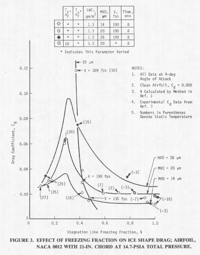
Those ice shapes and others with measure Cd values were plotted versus calculated leading edge freezing fraction (and other parameters).
This suggests that for this airfoil and this range of conditions, there is a peak effect near a stagnation line freezing fraction of 0.3 [see also the discussion in Conclusions of the "Ice Shapes and Their Effects" thread]. Slightly different values of freezing fraction would put one in the regions to either side of steep slopes, where a small difference in freezing fraction equals a large difference in Cd. Thus it is hard to determine a universal "close enough" tolerance on freezing fraction or any other variable.
Note that the freezing fraction values calculated in AEDC-TR-87-23 in differ slightly from those calculated with the method in the later NASA-CR-2004-212875. AEDC-TR-87-23 does not provide detailed example calculations to determine what the differences are.
Conclusions
CONCLUSIONS A study was conducted to investigate the possibility of achieving approximate icing similitude by comparing ice shapes against their corresponding icing scaling parameters. The results of this investigation indicate that:
1. The criteria for establishing icing similitude should be specified in advance of the simulation. Allowable similitude tolerances should also be specified.
2. A change in a particular icing scaling parameter may or may not indicate a change in ice shape (similitude). The reason for this is the functional dependency of a particular scaling parameter (Θ, Φ, N, Ac, Ko) on the icing test conditions (T, LWC, MVD, V, P) that caused the change in the ice shape.
3. It may be more indicative of similitude to consider changes in ice shape brought about by changes in the test conditions rather than changes of the icing scaling parameters.
4. The allowable tolerance in setting icing test conditions will depend upon the similitude application and the particular icing conditions at which the test is to be conducted (e.g., rime versus glaze ice region).
5. As long as the local icing conditions ensure rime ice accretions on the component under consideration (N is approximately > 0.7), similitude is easier to accomplish.
6. For specific temperatures, the LWC term can be decreased to levels that cause the icing surface thermodynamics to return to the rime ice accretion regime, and thereby allows use of the (LWC x V x t) term to achieve approximate similitude.
7. The ice scaling laws of Ref. 1 cannot be used to determine allowable tolerances in setting test conditions.
8. The effects of pressure (altitude) on icing similitude in the range studied herein are negligible and can be ignored in these cases. This does not consider the effects of icing due to pressure changes, internal to an engine, for example, nor does it consider how changes in free-stream altitude pressure may change local icing test conditions and, hence, affect ice shape.
9. Additional work is needed to develop other approaches to ice scaling. The ice scaling code employed in this study may be too restrictive.
Additional work
Extensive additional work on scaling was accomplished after AEDC-TR-87-23. However, a subsequent paper, [Bilanin, "Proposed Modifications to Ice Accretion/Icing Scaling Theory"], appears to impose even more restrictions. It would take much further testing and analysis to arrive at what I consider to be the "modern" reference method for scaling of unheated ice shapes, NASA/CR-2004-212875.
Critical ice shape selection
It is illustrative that the measurements shown in Figure 3 are not numerous enough to capture the peak Cd value with confidence (the lines drawn are speculative, not real curve fits). This is not because the tests were not planned well, but because it is hard to do. Finding such a peak is presumably what needs to be done to identify a critical ice shape.
To find such a peak in detail, options include:
- have numerous, tightly spaced test points in the test plan
- have some pre-knowledge that there is a peak near certain conditions, and plan several closely space test points near that
- during a test, plot points and realize there is an apparent peak, and add more test points near the peak
I would not say that for all airfoils and conditions there is a peak effect near freezing fraction of 0.3, but if you have no other information that might be a good place to start searching.
Not every test measures section Cd with ice. While I can find hundreds (perhaps in the low thousand) of measured ice shapes, I can only think of only a few dozen where Cd was measured (most of them herein) (and fewer with Cl measured.) Cd measurements add time and cost to a test.
There are technical challenges to measuring the section drag with ice with either a force balance or wake pressure survey. Among the challenges is that the ice is not always uniform over the span.
Also, while the measured section Cd with ice may be a useful relative value, it is not clear that it relates directly and linearly to airplane level values.
If Cd is not measured, how does one select a critical ice shape? Figure 10 of NASA-TM-83556 has probably been influential. The ice shapes with the largest Cd values have upper ice "horn" angles of about 45 degrees (209 km/h -5C, 338 km/h -2C and -5C).
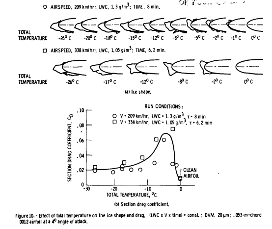
Figure 10 from NASA-TM-83556
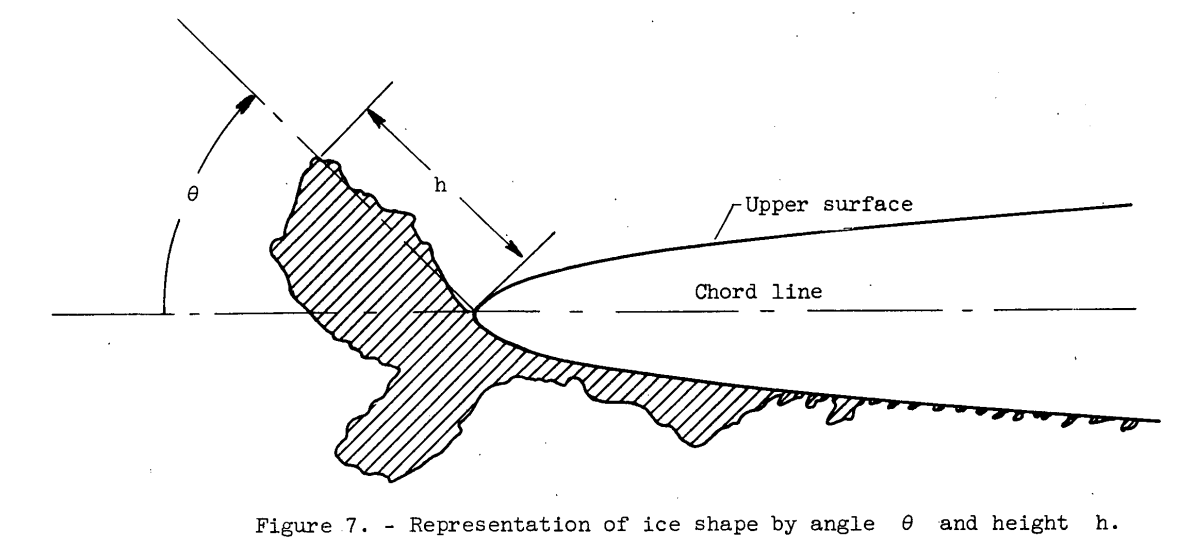
Figure 7 from NACA-TN-4151
While it was published well before NACA-TM-83556, the ice shapes from Wilder also have about a 45 degree horn angle:
Figure 6 from Wilder
And, even earlier, NACA-TN-4151 had maximum Cd values at an ice horn angle of 35 to 60 degrees, depending on the angle of attack, for a completely different (much thinner) airfoil.
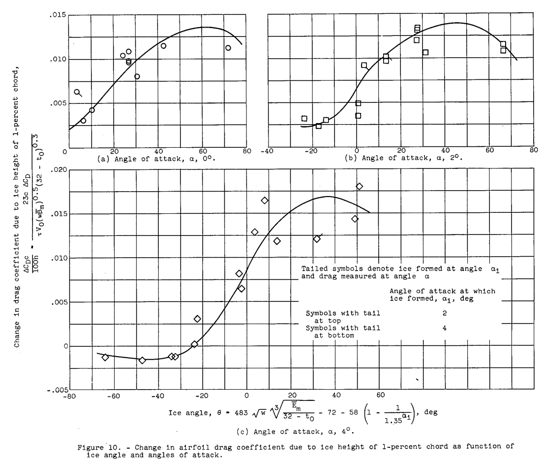
Figure 10 from NACA-TN-4151
If nothing else, it appears to be a long ingrained expectation of ice shapes.
Setting tolerances
While the stated subject of the publication was tolerances in icing tunnel tests, it ends up with little practical guidance:
1. The criteria for establishing icing similitude should be specified in advance of the simulation. Allowable similitude tolerances should also be specified.
4. The allowable tolerance in setting icing test conditions will depend upon the similitude application and the particular icing conditions at which the test is to be conducted (e.g., rime versus glaze ice region).
7. The ice scaling laws of Ref. 1 cannot be used to determine allowable tolerances in setting test conditions.
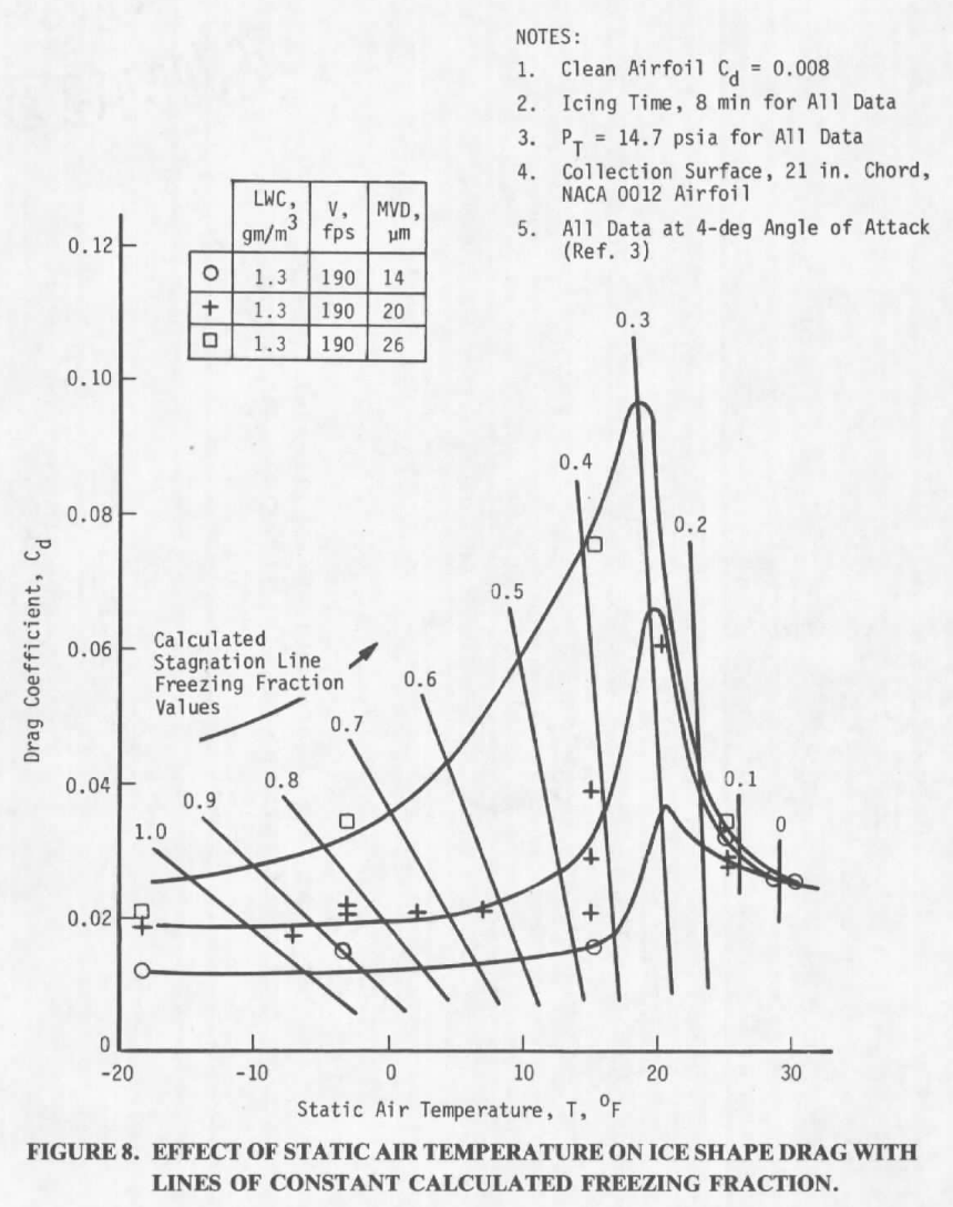
It is not clear how tolerances can be specified. If we pick for our "similitude application" as selecting ice shapes with the largest Cd effect, we expect glaze ice shapes to have the largest effect, as in Figure 10 from NASA-TM-83556 above. In Figure 8 above, a 1°F change in static temperature would appear to cause a significant change in Cd near the peak value. It is also not clear if, for example, a +/-10% tolerance on the LWC values is "good enough" or not.
Citations
AEDC-TR-87-23 cites seven publications:
- Ruff, Gary A.: Analysis and Verification of the Icing Scaling Equations AEDC-TR-85-30 Vol. 1 (Revised) apps.dtic.mil
- Bartlett, C. S. "An Analytical Study of Icing Simifitude for Aircraft Engine Testing." AEDC-TR-86-26, DOT/FAA/CT-86/35, October 1986. apps.dtic.mil
- Olsen, William, Shaw, Robert, and Newton, James: Ice Shapes and the Resulting Drag Increase for a NACA 0012 Airfoil. NASA-TM-83556, 1984. ntrs.nasa.gov
- Flemming, R. J. and Lednicer, D. A. "High Speed Ice Accretion on Rotorcraft Airfoils." United Technologies Corporation, NASA-CR-3910, August 1985.
- Langmuir, E. and Blodgett, K. B. "A Mathematical Investigation of Water Droplet Trajectories." General Electric Co., ATI 25 223, February 1946.
- Willbanks, C. E. and Schulz, R. J. "Analytical Study of Icing Simulation for Turbine Engines in Altitude Test Cells." AEDC-TR-73-144 (AD-770069), November 1973. apps.dtic.mil
- Pheifer, G. D. and Maier, G. P. "Engineering Summary of Powerplant Technical Data." FFA-RD-77-76, July 1977. archive.org
An online search 2 found 7 citations of "An Empirical Look at Tolerances in Setting Icing Test Conditions with Particular Application to Icing Similitude". [I view this as under-valued for the excellent technical content it contains, but not quite a "lost gem".]
Notes
-
Bartlet, C. S.: "An Empirical Look at Tolerances in Setting Icing Test Conditions with Particular Application to Icing Similitude". AEDC-TR-87-23, DOT/FAA/CT-87-31, August, 1983. apps.dtic.mil ↩