"It is thus desirable to have an economical method for solving the basic water droplet trajectory equations for an arbitrary airfoil." 1
The Use of Ko for Impingement Correlations
The use of a modified water droplet inertia parameter Ko permits consolidation into only a few graphs of most of the published water drop trajectory data.
From Werner, J. B., Ice Protection Investigation for Advanced Rotary-Wing Aircraft. 1
(This is a candidate for "The Greatest Thing That You Have (Probably) Never Read").
To paraphrase NACA-TN-3839 2, the studies in this Impingement on Surfaces thread "were a rather ad hoc collection of shapes and sizes". One unifying parameter emerged to correlate the results, the "Ko" modified water drop inertia parameter.
"Mathematical Investigation of Water Droplet Trajectories" 3
"Mathematical Investigation of Water Droplet Trajectories" 3 defined a term Ko (see the link for definitions of other terms):
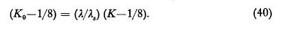
Ko is not given a name, it is only defined in relation to K:
The quantity Κ that occurs in Eqs. (4) and (5) measures the inertia of the droplet and varies in proportion to the density of the particle and increases with its size.
A correlation of Ko to Em for cylinders was provided (for a limited range of K values):
Calculation of Em for low values of Κ
Having found Ko by Eq. (40) and the data of Table I, we then calculate Em by Eqn. (33) using Ko as the value of K. This method of calculation was given as a semi empirical method in the report, "Super Cooled Water Droplets in Rising Currents of Cold Saturated Air", Part I, page 275, by I. Langmuir, sent to Materiel Command , Wright Field. When the D. A. data were compared with the calculated values of Em, it was found that the following small correction would bring the calculated values into good agreement with the observed values, for all values of φ. The correction was therefore included in the procedure for calculating Em.For Κ in the range from 0.125 to 1.1;

"Determination of drop trajectories by means of an extension of Stokes' Law" (1952) 4
A version of Ko was generalized to apply to almost any surface.
SUMMARY
Trajectory data were determined for drops in air flowing over a cylinder, a sphere, a ribbon, and several airfoils, by reduction of the number of parameters previously used. One trajectory data curve for each body was thus obtained where an entire family of curves was previously necessary.
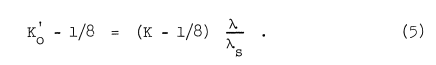
This reduction of the number of parameters was suggested by Langmuir.Langmuir and Blodgett found that results obtained by the differential analyzer solution of (1) and (2) were in good agreement with values resulting from calculations based on Ko', an adjusted value of K, and Stokes' Law, where (for flow around a cylinders):
λ is the distance a droplet will travel if projected into still air with an initial velocity of U when the drag coefficient follows values given in reference 1.
λ/λs is obtained from:
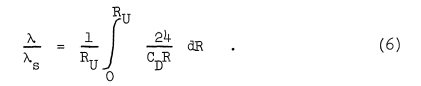
λ/λs is therefore an average value of CDR/24 for a drop projected into still air with an initial velocity U and final velocity zero. If, for the case of still air, Eqs. (a) and (2) are solved by using an average value of CDR/24K, there is a K for which we can apply Stokes' Law and obtain the same trajectory. Ko is defined by:
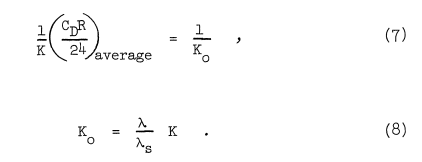
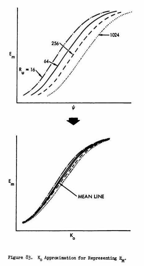
If this adjustment of K is extended to the case of a varying air velocity field, the curves of Figures 1-20 result.
An examination of the curves suggests that for each body, instead of a wide spread of curves as shown in the Guibert and Langmuir and Blodgett reports, only one curve is then necessary.
Here we will look at the Em curves (only). There are also curves for βmax and impingement limits.
The values are similar for most values of Ko. However, for example at K=0.4, the spread in values (about 0.06 Em) are approaching the individual values (0.13 to 0.19), indicating that a selected Ko correlation (not shown) would be less accurate at lower Ko values.
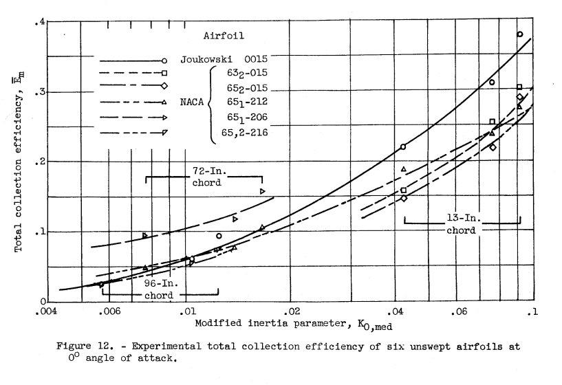
A later publication, "Ice Protection Investigation for Advanced Rotary-Wing Aircraft" 1,
does show an example of a selected "mean line" Ko approximation.
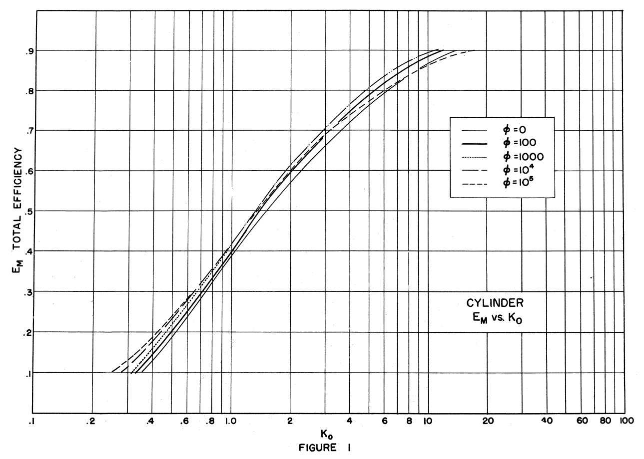
Two of the airfoils from the review Impingement on Airfoils were analysed:
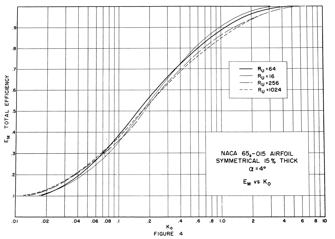
The Ko approximation works well for both of those airfoils.
Remember the ribbon from Impingement on Other Surfaces (NACA-TN-3658)?
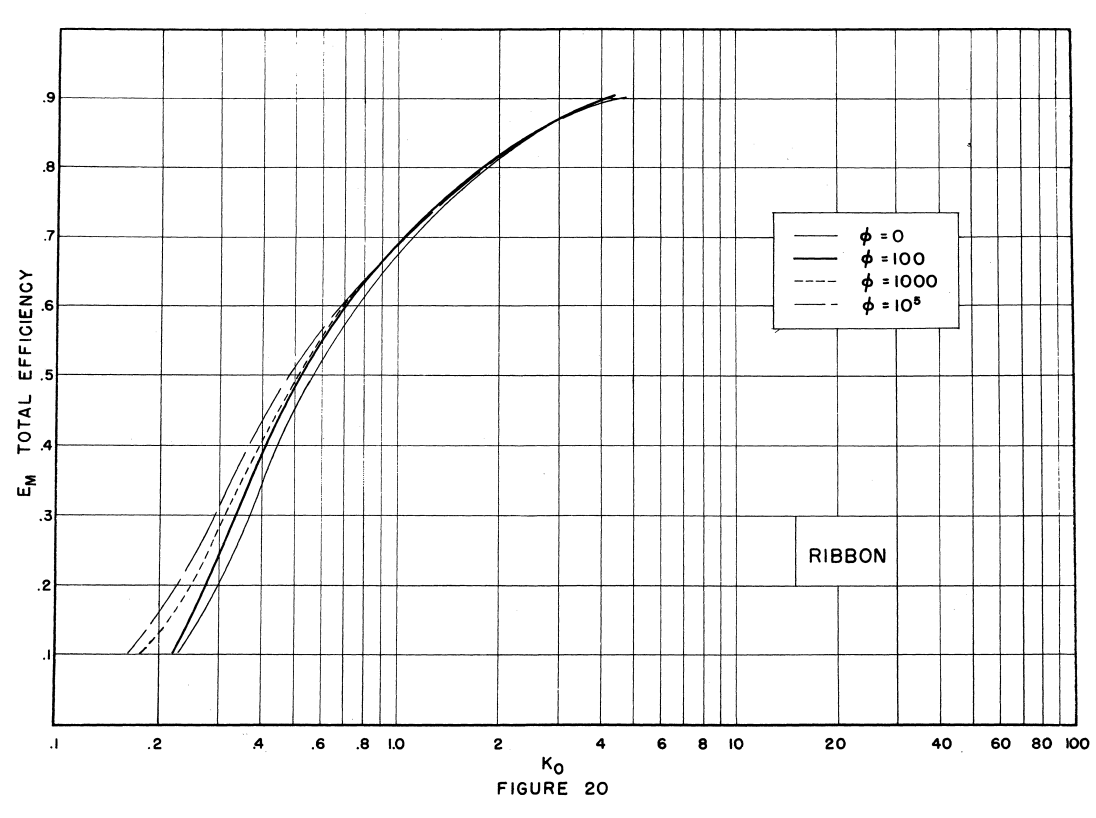
Fortunately, most applications for a ribbon will be "thin", so that Ko is likely to be high, and the Ko approximation rather good.
While "Determination of drop trajectories by means of an extension of Stokes' Law" was published in 1952, there was no mention of it or Ko in the University of Michigan Airplane Icing Information Course in 1953, where Tribus presented "A new method for calculating water-droplet trajectories about streamlined bodies" from 1951.
The Post NACA-era
NACA-TN-3839 used Ko to "correlate to the extent possible" experimental results for different airfoils.
We see the same data replotted in ADS-4, “Engineering Summary of Airframe Icing Technical Data” 5:
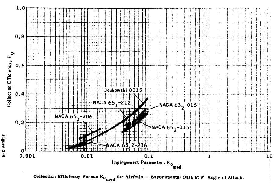
Unfortunately, ADS-4 does not cite "Determination of drop trajectories by means of an extension of Stokes' Law", nor any work by Tribus. It does cite the NACA publications noted above, and a publication that I have not been able to find 6.
The same figure (renumbered) appears in the FAA Aircraft Icing Handbook 7.

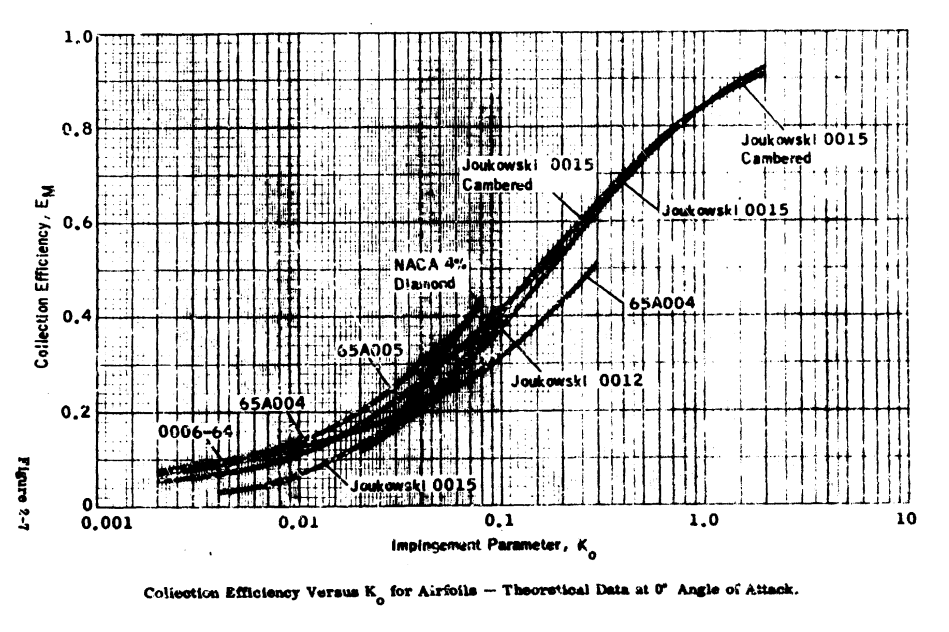
Figure 2-7 shows similar use of Ko in ADS-4 for theoretical Em values, which cover a broader range of Ko values:
Digital Computing
As we saw in Methods of Water Drop Impingement Quantification, methods other than digital computers were used in the NACA-era.
By the close of the NACA-era, Design Manuals such as ADS-4 (1964) provided impingement plots Ko correlated impingement data. Solution by computers are mentioned, but no examples were given:
The calculation of droplet trajectories can be extremely tedious and time consuming; however, the problem can be set up and solved using modern high-speed electronic computers.
Wilder 8 mentions the use of digital computers for impingement calculations in industry in 1969.
There are many currently available options for calculating impingement on a surface. LEWICE 9 is one example. For potential flow, the air flow field calculations are generally a small portion of the total run time for impingement calculations. However, for viscid flow calculations, the air flow field calculations dominate the total run time required.
Continuing uses of the Ko parameter
The parameter Ko is still useful today for illustrating impingement trends.
Here are examples from the "Aircraft Icing Handbook" 7:
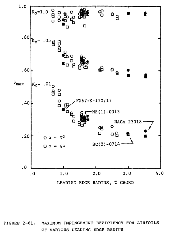
For airfoils, Bragg (references 2-12, 2-33, and 2-34) has studied the effect of geometry on droplet impingement. Several airfoil geometry terms were considered, including: maximum thickness and its location, maximum camber and its location, and leading edge radius. One of the strongest relationships found was that between the airfoil leading edge radius and the maximum impingement efficiency.
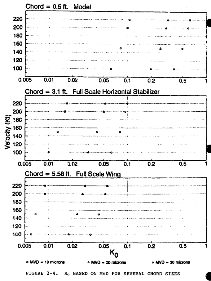
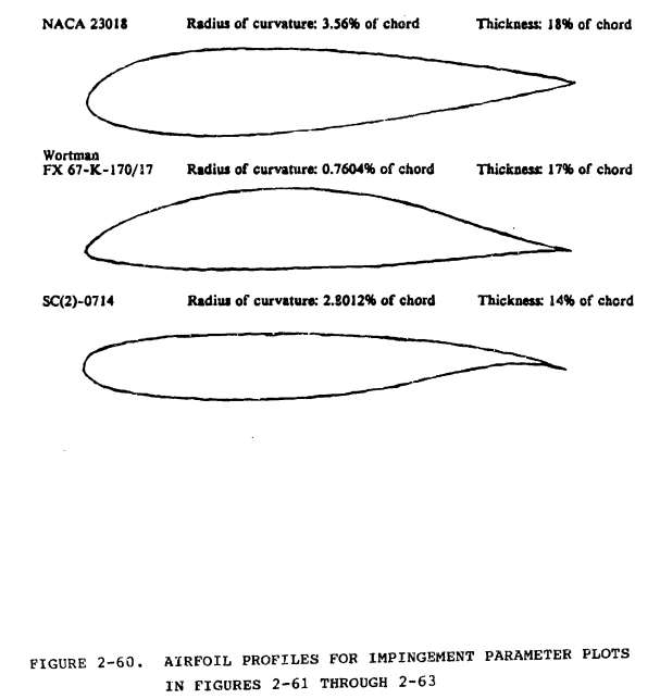
In figure 2-61, βmax is plotted versus leading edge radius for the thirty airfoils of reference 2-33. (Points for four airfoils are indicated by solid symbols and labeled; see figure 2-60 for profiles.) Data are plotted for two angles of attack and three modified inertia parameters. Note that at Ko = 0.01 (within the "typical" range for a wing section of a general aviation aircraft - see figure 2-4) there is a strong relationship between leading edge radius and βmax. For an airfoil with leading edge radius of 0.8 percent chord and Ko = 0.01, βmax is approximately 0.5, but drops to around 0.25 for a leading edge radius of 2.0 percent chord. Also note that the dependence decreases markedly with increasing Ko and that Smax decreases slightly with increasing angle of attack for each value of Ko. Finally, note that variation in βmax for a particular value of the leading edge radius arises from other characteristics of the airfoils, since they differ in more than leading edge radius.
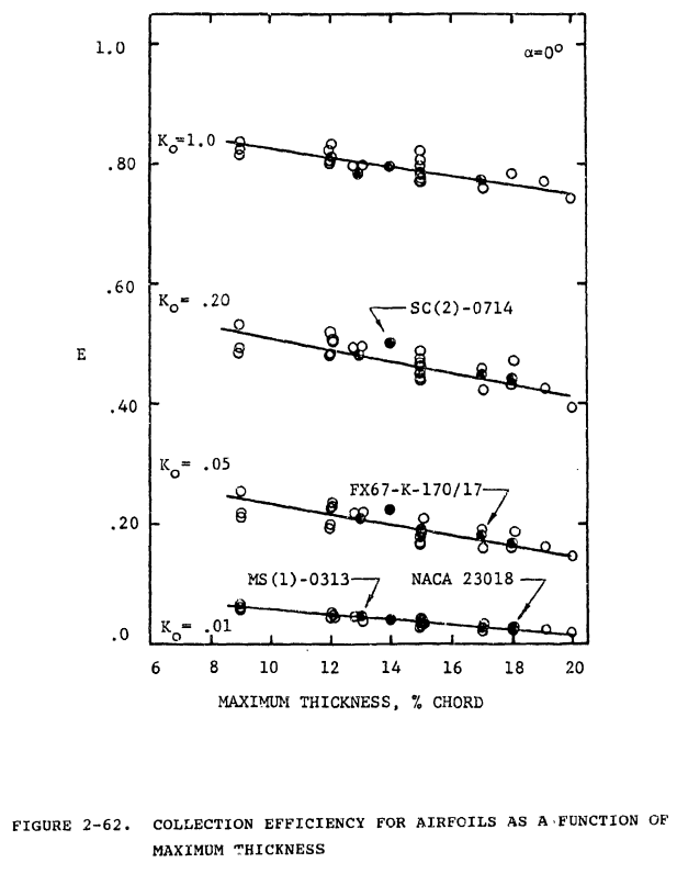
Another relationship is that between airfoil maximum thickness and collection efficiency, E. In figure 2-62, E is plotted as a function of maximum thickness for all thirty airfoils and for four Ko's. For all Ko's shown, E decreases as the airfoil thickness increases. However, the effect becomes less pronounced with decreasing Ko and for Ko = 0.01 is quite slight (note also that E < 0.10 for all airfoils for this condition). Figure 2-62 indicates that thicker airfoils (and bodies in general) are less efficient droplet collectors with respect to the width h of their projected frontal area. This does not mean, however, that thicker airfoils accrete less mass of ice. Figure 2-63 shows ΔY0 as a function of airfoil maximum thickness for the same conditions as figure 2-62. Here the opposite relationship is seen, that is, ΔY0 increases as airfoil thickness increases, the effect being very pronounced for large Ko (although non-existent for Ko = 0.01). Since E = -ΔY0/h, it follows that E decreases with increasing airfoil thickness because h increases faster than ΔY0, but since mass of ice accreted is directly proportional to ΔY0, it is essentially independent of airfoil thickness for Ko increasing airfoil thickness for larger Ko.
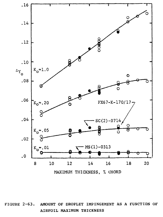
I will emphasize:
This does not mean, however, that thicker airfoils accrete less mass of ice.
This is corrects a mis-conception that I have heard more than once. E is a dimensionless water catch efficiency parameter. However, in most practical applications, one is concerned with the dimensional amount of water catch, and something like Figure 2-63 is useful to illustrated that.
Figure 81 from 2 provides another useful illustration.
The total ordinate, "Y", divided by the maximum airfoil thickness, "d", is called Em, the efficiency of water catch. Figure 81 depicts the droplet trajectories around a 2-D airfoil at an angle of attack α.
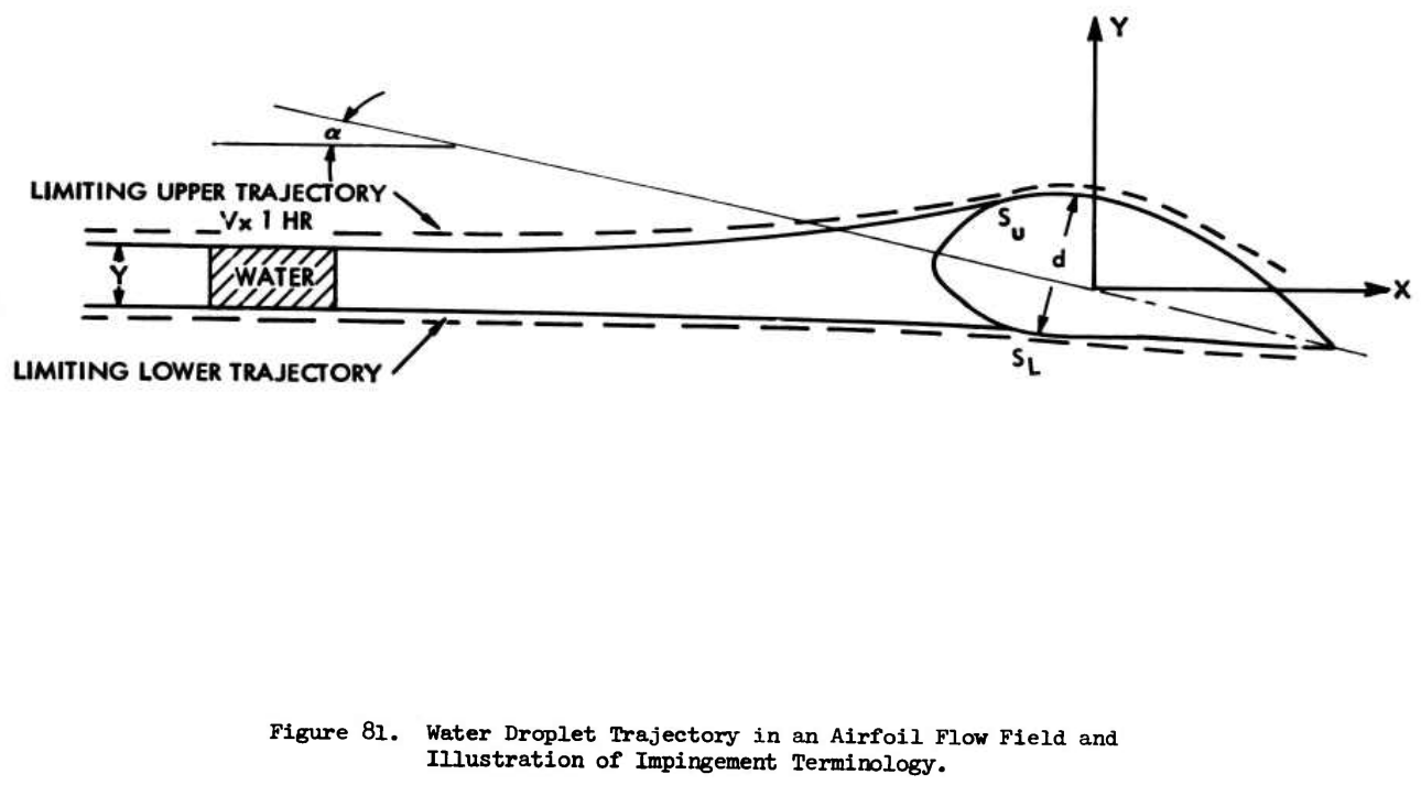
The block labeled "WATER" is the amount of water that will strike the airfoil. A thinner airfoil might have a water catch efficiency near one, and the limiting trajectories would be nearly straight lines, but both airfoils would catch nearly the same amount of water.
(A small correction to Figure 81. Conventionally, Em is calculated with projected airfoil height at α, not the maximum airfoil thickness at α=0. However, this does not affect the point illustrated.)
Why is Em of such interest?
[Emphasis added.]
Presentation of Tribus' data using the Ko parameter showed the close grouping of data points instead of the usual family of curves. A mean line through the Ko curves showed that the deviations in efficiency of water catch and limits of ice impingement were generally about 10 percent or less. (Exceptions were Em data for the cylinder and ribbon at low Ko values for which the deviations from the mean line were higher than 10 percent.) This is accurate enough for most preliminary calculations involving the heat requirements for anti-icing an airfoil.
As we saw previously in the Icing Wind Tunnel Test Thread, the "Manual of Scaling Methods" 10 uses Ko correlations for a cylinder to approximately the impingement on an airfoil, particularly for βmax. This provides "an economical method for solving the basic water droplet trajectory" for a use where a lot of detail is not required.
Citations
"Determination of drop trajectories by means of an extension of Stokes' Law" had nine citations found at scholar.google.com.
I believe that as it was not cited in either ADS-4 or “Aircraft Icing Handbook", its contributions and importance are under-appreciated.
This is an instance of the work of Tribus being under-appreciated. Another instance is the thermodynamics of ice formation. While Messinger clearly credited Tribus in "Equilibrium Temperature of an Unheated Icing Surface as a Function of Airspeed" 11 this was largely forgotten. "Equilibrium ..." is cited over 800 times at google.scholar.com, while "Determination ..." in not even in double-digits.
In the NACA literature, I found six citations of "Determination ...":
- Serafini, John S.: Impingement of Water Droplets on Wedges and Double-Wedge Airfoils at Supersonic Speeds. NACA-TR-1159, 1954. (Supersedes NACA-TN-2971.) ntrs.nasa.gov
- Brun, Rinaldo J., and Vogt, Dorothea E.: Impingement of Cloud Droplets on 36_5-Percent-Thick Joukowski Airfoil at Zero Angle of Attack and Discussion of Use as Cloud Measuring Instrument in Dye-Tracer Technique. NACA-TN-4035, 1957. ntrs.nasa.gov
- Lewis, William, and Brun, Rinaldo J.: Impingement of Water Droplets on a Rectangular Half Body in a Two-Dimensional Incompressible Flow Field. NACA-TN-3658, 1956. ntrs.nasa.gov
- Gelder, Thomas F., Smyers, William H., Jr., and von Glahn, Uwe H.: Experimental Droplet Impingement on Several Two-Dimensional Airfoils with Thickness Ratios of 6 to 16 Percent. NACA-TN-3839, 1956. ntrs.nasa.gov
-
Lewis, James P., and Ruggeri, Robert S.: Experimental Droplet Impingement on Four Bodies of Revolution. NACA-TN-4092, 1957. ntrs.nasa.gov
-
Gelder, Thomas F.: Droplet Impingement and Ingestion by Supersonic Nose Inlet in Subsonic Tunnel Conditions. NACA-TN-4268, 1958. ntrs.nasa.gov
Related
This is the conclusion of the Water Drop Impingement on Surfaces thread.
Notes
-
Werner, J. B., Ice Protection Investigation for Advanced Rotary-Wing Aircraft. US Army Air Mobility Research and Development Laboratory, 1973. apps.dtic.mil ↩↩↩
-
Gelder, Thomas F., Smyers, William H., Jr., and von Glahn, Uwe H.: Experimental Droplet Impingement on Several Two-Dimensional Airfoils with Thickness Ratios of 6 to 16 Percent. NACA-TN-3839, 1956. ntrs.nasa.gov ↩↩
-
Langmuir, Irving, and Blodgett, Katherine B.: A Mathematical Investigation of Water Droplet Trajectories. Tech. Rep. No. 5418, Air Materiel Command, AAF, Feb. 19, 1946. (Contract No. W-33-038-ac-9151 with General Electric Co.) books.google.com ↩↩
-
Sherman, P., John Sharpless Klein, and Myron Tribus. Determination of drop trajectories by means of an extension of Stokes' Law. 1952. deepblue.lib.umich.edu ↩
-
Bowden, D.T, et.al., “Engineering Summary of Airframe Icing Technical Data”, FAA Technical Report ADS-4, General Dynamics/Convair, San Diego, California, 1964. apps.dtic.mil ↩
-
NA-63-303, "Use of the Ko Correlation in Preliminary Design and Scale Model Icing," Frederick R. Weiner, North American Aviation, Inc. (Presented at Spring Meeting of Aircraft Air-Conditioning Forum, Los Angeles, California, March 21, 1963). This has been added to the Hard to find publications list. ↩
-
“Aircraft Icing Handbook Volume 1.” DOT/FAA/CT-88/8-1 (1991) apps.dtic.mil.
Also note that there was a perhaps little known update in 1993 (that did not affect the pages of interest herein): apps.dtic.mil. ↩↩ -
Wilder, Ramon W.: "Techniques used to determine Artificial Ice Shapes and Ice Shedding, Characteristics of Unprotected Airfoil Surfaces" in Anon., "Aircraft Ice Protection", the report of a symposium held April 28-30, 1969, by the FAA Flight Standards Service; Federal Aviation Administration, 800 Independence Ave., S.W., Washington, DC 20590. apps.dtic.mil. ↩
-
Wright, William. User's manual for LEWICE version 3.2. No. E-15537. 2008. NASA/CR—2008-214255 ntrs ↩
-
Anderson, David N.: Manual of scaling methods. No. E-14272, NASA/CR-2004-212875. 2004. ntrs.nasa.gov ↩
-
Messinger, B. L.: Equilibrium Temperature of an Unheated Icing Surface as a Function of Airspeed. Preprint No. 342, Presented at I.A.S. Meeting, June 27-28, 1951. ↩