"Although the airfoils used in these studies were a rather ad hoc collection of shapes and sizes, this report makes these data generally available and correlates the data as much as possible."
From NACA-TN-3839.
NACA-TN-2931, "A Method for Determining Cloud-Droplet Impingement on Swept Wings"
and
NACA-TN-3839, "Experimental Droplet Impingement on Several Two-Dimensional Airfoils with Thickness Ratios of 6 to 16 Percent"
Summary
Several airfoils were analyzed and tested for water-drop impingement in the NACA-era.
Abstract
The rate and area of cloud droplet impingement on several two-dimensional swept and unswept airfoils were obtained experimentally in the NACA Lewis icing tunnel with a dye-tracer technique. Airfoil thickness ratios of 6 to 16 percent; angles of attack from 0° to 12°, and chord sizes from 13 to 96 inches were included in the study. The data were obtained at 152 knots and are extended to other conditions by dimensionless impingement parameters.
In general, the data show that the total and local collection efficiencies and impingement limits are primary functions of the modified inertia parameter (in which airspeed, droplet size, and body size are the most significant variables)and the airfoil thickness ratio. Local collection efficiencies and impingement limits also depend on angle of attack. Secondary factors affecting impingement characteristics are airfoil shape, camber, and sweep angle. The impingement characteristics obtained experimentally for the airfoils were within +/-10 percent on the average of the characteristics calculated from theoretical trajectories. Over the range of conditions studied, the experimental data demonstrate that a specific method can be used to predict the impingement characteristics of swept airfoils with large aspect ratios from the data for unswept airfoils of the same series.
Discussion
Airfoils studied
Several airfoils were analyzed and tested for water-drop impingement in the NACA-era. The airfoil sections are summarized below.
NACA-TN-1397 2 Joukowski 12% symmetric AOA=0
NACA-RM-A905 3 Joukowksi 15% symmetric, includes camber case
NACA-TN-2931 4 NACA 651-212, includes swept cases, includes swept cylinder
NACA-TN-2952 5 NACA 651-212, 651-208
NACA-TN-3047 6 NACA 65A004, 651-212, 651-208
NACA-TR-1159 7 Symmetrical double-wedge
NACA-TN-3155 8 NACA 65A004
NACA-TN-3586 9 NACA 65A004
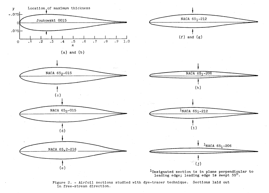
NACA-TN-3839 1 Joukowski 0015, NACA 632-015, 652-216, 651-212, 651-206, includes swept cases
NACA-TN-4035 10 Joukowski 36.5%
We will review two of the publications here, NACA-TN-2931 and NACA-TN-3839.
NACA-TN-2931 proposes a method of analyzing the impingement on yawed or swept by considering a plane normal to the leading edge and using the normal component of the velocity in the impingement analysis.
NACA-TN-3839 is the culmination of these studies, and will be reviewed in detail. It compares test and analysis, and also validate the theoretical effect of sweep studied in NACA-TN-2931. In addition, it has one of the best summaries of the dye tracer method, and its use to determine water-drop size distributions in a water spray. It is long (80 pages), with most of the pages being detailed figures.
I will briefly mention NACA-TN-4025 here, although it may merit a full review to itself. The rather thick 36.5% Joukowski airfoil is offered as an alternative to the cylinder as a dye-tracer instrument. Benefits include potentially better discrimination of drop sizes when used to determine drop-size spectra. The effects of boundary layers and aft flow separation are also discussed. Both of those effects appear to be small, as impingement calculated with potential flow, which does not include either of those effects, compares well to experimentally measured data.
NACA-TN-2931
SUMMARY The general effect of wing sweep on cloud-droplet trajectories about swept wings of high aspect ratio moving at subsonic speeds is discussed. A method of computing droplet trajectories about yawed cylinders and swept wings is presented, and illustrative droplet trajectories are computed.
A method of extending two-dimensional calculations of droplet impingement on nonswept wings to swept wings is presented. It is shown that the extent of impingement of cloud droplets on an airfoil surface, the total rate of collection of water, and the local rate of impingement per unit area of airfoil surface can be found for a swept wing from two-dimensional data for a nonswept wing. The impingement on a swept wing is obtained from impingement data for a nonswept airfoil section which is the same as the section in the normal plane of the swept wing by calculating all dimensionless parameters with respect to flow conditions in the normal plane of the swept wing.Because of its geometric and aerodynamic simplicity, the problem of impingement on a yawed circular cylinder will be considered first. The method developed for the cylinder will apply equally well to a swept wing, and this application will be discussed in detail in a subsequent section.
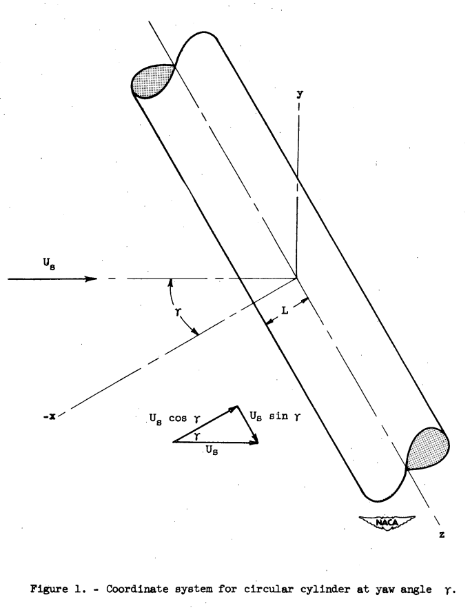
The incompressible nonviscous velocity field around a yawed circular cylinder of infinite span can be divided into components in the x-, y-, and z-directions, as shown in figure 1. The right-rectangular coordinate system is established so that the center line of the cylinder coincides with the z-axis. The angle of yaw y is measured with respect to the negative x-axis. The flow in the xy-plane (normal plane) is the same as the flow about a nonyawed circular cylinder which has a free-stream velocity equal to the component of the free-stream velocity in the normal plane U cos γ. The velocity component in the z-direction is a constant throughout the flow field, and the magnitude of the component is determined by the projection of the free-stream velocity on the z-axis U sin γ.
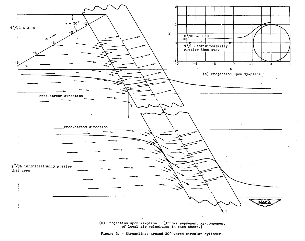
The effect of yaw on the streamlines and local air velocity vectors can be illustrated by an example in which the flow field about a yawed circular cylinder is presented. For this example, the yawed. cylinder is assumed oriented in an x,y,z-coordinate system as shown in figure 1. The angle of yaw γ with respect to the free-stream direction is 30°. The projection of two streamlines, selected for illustration, upon the xy- and xz-planes is shown in figure 2. (The method of calculation is given in appendix A.) Also shown are the projections of velocity vectors upon the xz-plane at various points in the sheet (surface perpendicular to the xy-plane containing the streamline) which contains each streamline. Considerable deviation of the streamlines from the projection of the free-stream direction in the xz-plane is indicated in the figure. The curvature of the streamlines in the xz-plane is due to the fact that, whereas the Ux component changes in magnitude with x and. y, Uz is a constant independent of x or y. The z velocity component u is a constant throughout the flow field, because in a frictionless fluid it is equal only to the projection along the z-axis of the free-stream velocity U and is not influenced by the perturbation velocity of the cylinder in the xy-plane. The maximum curvature of the streamline projections in the xz-plane takes place in those streamlines located near a surface defined by the stagnation stream-lines. This maximum curvature of the stagnation streamlines is to be expected, because along a stagnation line where u becomes small (close to the body), uz is relatively predominant and the displacement is primarily in the z-direction.
Sample Droplet Trajectories About Yawed Cylinder
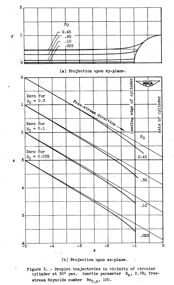
Three-dimensional droplet trajectories were calculated for a yawed cylinder for conditions where the inertia parameter Kn is equal to 2.78 and the free-stream Reynolds number in the normal plane Re0,n equal to 100. The projections upon the xy- and xz-planes of typical droplet trajectories are shown in figure 3. The starting ordinate (at x = -∞) in the xy-plane for each trajectory is given by the value of y_o in the figure.Swept Wings The calculation of droplet trajectories about a swept wing can be accomplished by the method used for the yawed cylinder in the preceding sections, if the flow field about a swept wing is approximated (except near the fuselage and wing tips) by the incompressible nonviscous flow about an Infinite-span wing of zero taper at an angle of yaw equal to the sweep angle. This approximation is valid for wings of high aspect ratio and small taper.
The nonviscous flow field about a yawed wing of infinite span can be obtained in the same manner as that for the yawed cylinder by determining the components in the normal (xy) plane (fig. 4) and the component parallel to the leading edge (z-direction). The flow field in the normal plane is determined from two-dimensional theory by using the airfoil section in the normal plane and the component of the free-stream velocity in the normal plane U_s cos γ. As before, the z-component is constant throughout the flow field, being simply the projection of the free-stream velocity upon the z-axis U_s sin γ.
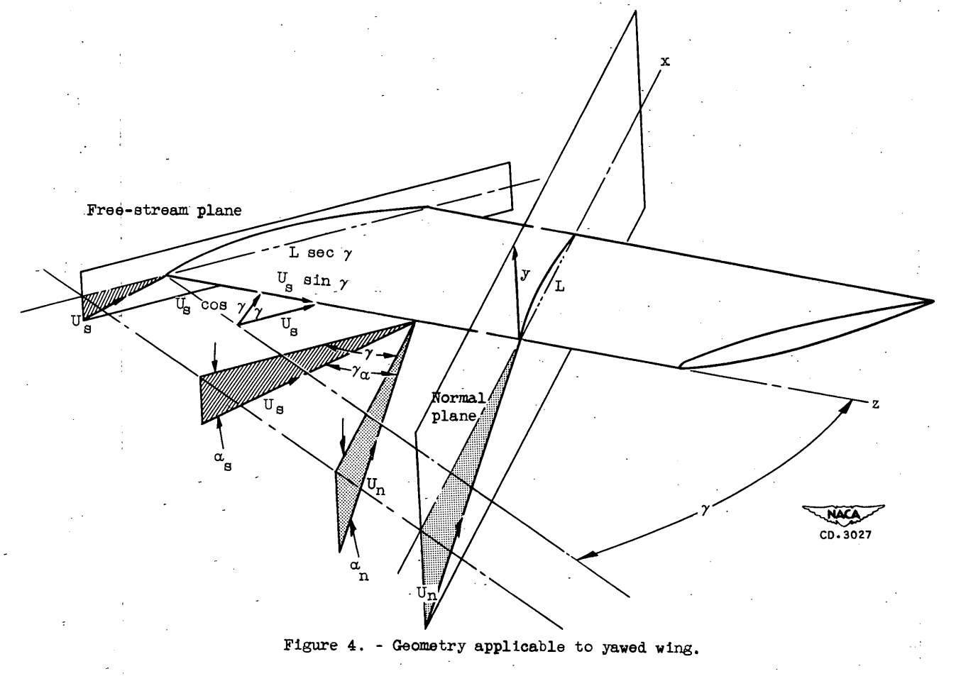
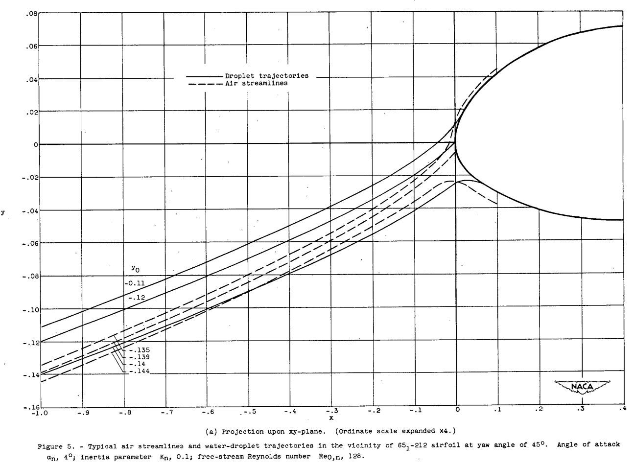
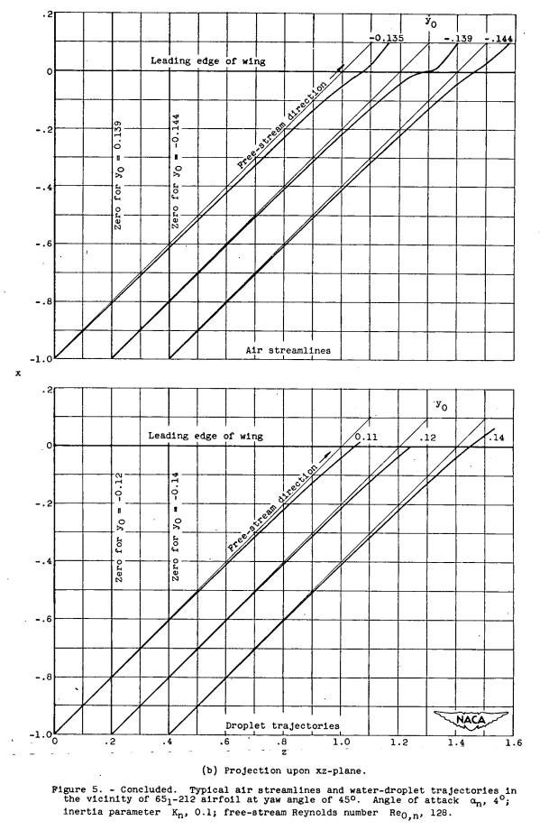
When the swept wing is at a free-stream angle of attack α_s (fig. 4), the effective angle of attack in the normal plane, to a close approximation, is α_n = α_s sec γ and the components of the free-stream velocity are U sin ra. and U_s cos γ where γ_α is the angle between U and U_n. For small angles of attack, γ_α is for all practical purposes equal to γ and therefore γ can be used when calculating the components of the free-stream velocity; however, the corrected angle of attack α_s sec γ must be used in obtaining the flow field in the normal plane. Air streamlines about a 651-212 airfoil-at 45° yaw and an angle of attack in the normal plane of 4° (α_s = 2.8°) are shown in figure 5. The projection of three streamlines on the xy-plane from x = -1 to 0.1 is shown in figure 5(a), and the projection on the xz-plane is shown in figure 5(b). The method used. to obtain the streamlines is given in appendix B. As for the cylinder, the projections of the streamlines in the xz-plane deviate from the projection of the free-stream direction because of changes in U_x. The deviation from the projection of the free-stream direction is considerably less for the airfoil than for a cylinder with the same chord length, as would be expected from comparison of the velocity field of a thin body with that of a blunt body.
Sample Droplet Trajectories About Yawed Wing
The projections upon the xy- and xz-planes of typical droplet trajectories about a 651-212 airfoil with α_s = 2.8° (α = 4°) and at a yaw angle of 45 are shown in figure 5 for values of K = 0.1 and Re0,n = 128. As in the case of the air streamlines, there is less curvature of the xz-projection of the trajectory for the airfoil than for the relatively blunt cylinder. For example, up to about 1 chord length (x = -1, fig. 5(b)) ahead of the wing the droplets are essentially undeviated from the free-stream plane; whereas, for the cylinder they are undeviated only up to about 2 diameters (x = -5, fig. 3) ahead of the cylinder.
CONCLUSIONS An analysis of the general effect of sweep on the droplet trajectories about a swept airfoil and a method of calculating the droplet trajectories have been presented. The extent of impingement of cloud droplets on the airfoil surface, the rate of collection of total water in droplet form, and the local rate of impingement per unit area of the airfoil surface can be found for a swept wing from two-dimensional data for a nonswept wing with the same airfoil section as the section in the normal plane of the swept wing. The values of the dimensionless parameters required in order to interpret the two-dimensional data are calculated with respect to the normal plane of the swept wing rather than with respect to the free-stream plane as is the usual procedure for nonswept wings.
NACA-TN-3839
Spray water-drop size distribution
Spray Cloud Properties
The cloud total liquid-water content was obtained by collecting dye from the spray cloud in an aspirating device (a tube that draws in air and liquid water at free-stream conditions, ref. 15). The inlet velocity of the device was always within 1 percent of the free-stream value, denoting theoretically a 100-percent collection efficiency.
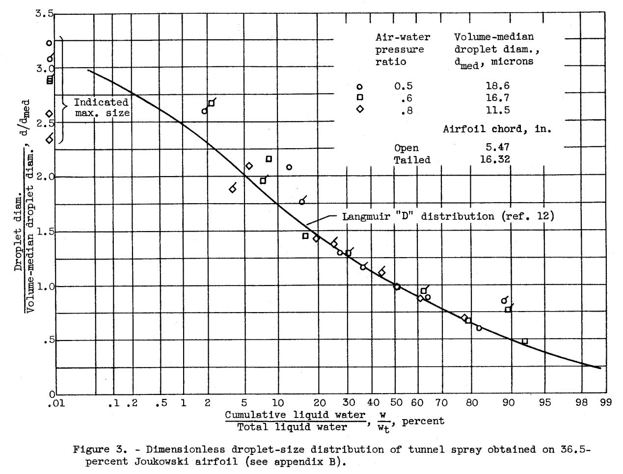
The droplet-size distribution was determined by the method outlined in reference 15, in which the experimental impingement rates for cylinders are related to theoretical data for similar cylinders. In the present study, however, small 36.5-percent-thick Joukowski airfoils were used instead of cylinders. The absolute values of droplet size from this airfoil section (see appendix B) generally confirm those obtained from the cylinders of reference 15, but the body size trend is reduced from that of reference 15.
The ratio of droplet diameter to volume-median diameter <1> is presented in figure as a function of the ratio of cumulative liquid-water content to total liquid-water content. The volume-median droplet diameters are believed accurate within +/- 6 percent. These data are from the aspirator and 36.5-percent Joukowski airfoil analyses for the three spray conditions (air-water pressure ratios) studied.<1> Volume-median droplet diameter is that diameter for which half the total liquid-water content is contained in droplets larger than the volume median and half in droplets smaller than the volume median.
Reference 15 is NACA-TN-3338.
"correlates the data as much as possible"
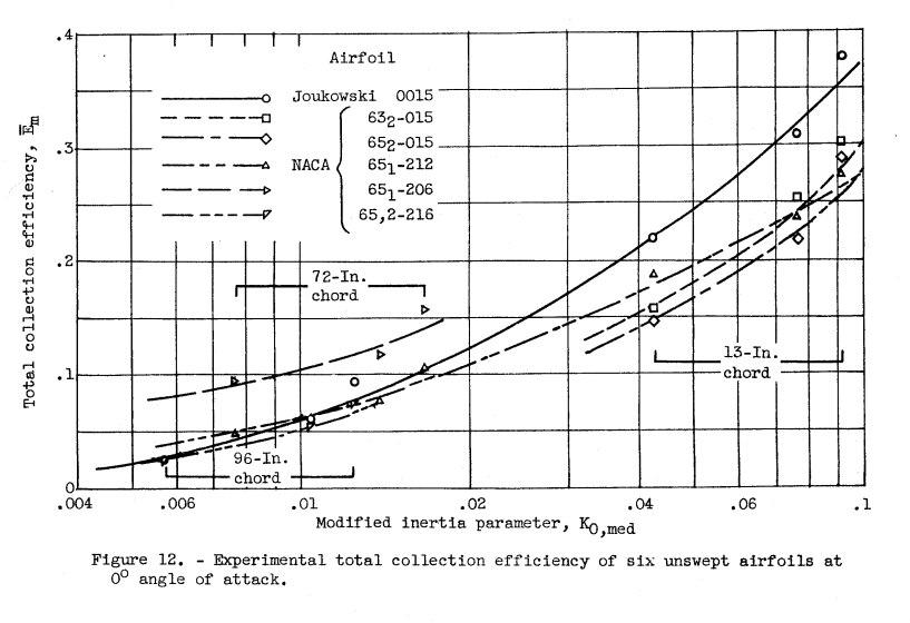
Variation of E_m with K0,med.
The total collection efficiency of an airfoil Em increases as K0,med increases (fig. 12). These data are plotted from table I for an angle of attack of 0°. In the range of K0,med < 0.02 the increase in Em with a decrease in the thickness ratio is readily apparent in figure 12 for airfoils of the same series and camber. For example, at 0° angle of attack and K0,med of 0.01 the Em values for the NACA 651-206, 651-212, and 652-216 airfoil sare 0.105, 0.06, and 0.05, respectively. These airfoils, although their numbering systems are somewhat different, are of the same series, differing primarily in thickness ratio and only to a minor degree in leading-edge radius and location of maximum-thickness point. These latter differences are considered of secondary significance in the evaluation of total collection efficiency. Reversals of this change in Em with thickness ratio may occur at high K0,med values (K0,med > 0.02), especially as the thickness ratio approaches 6 or 4 percent.
These types of figures will be included in later Design Manuals, such as ADS-4.
The effect of sweep
Correlation of Effect of Airfoil Sweepback
The experimental impingement data substantiate the method of reference 14 for predicting the impingement on a swept airfoil from data obtained on an unswept airfoil where (1) the wing can be considered two-dimensional or has a high aspect ratio and (2) the airfoil section in a plane perpendicular to the leading edge of the swept airfoil is the same section as that of the unswept airfoil. The application of the method of reference 14 to the experimental impingement data presented herein is discussed in appendix C. Typical experimental values of local collection efficiency β as a function of s for the 35° swept (NACA 651-212 and 651-206) airfoils are presented for angles of attack (referenced to freestream velocity direction) of 0° and 4.3° in figures 18(a) and (b), respectively. The faired lines of figure 18 represent the β values calculated from the unswept experimental data by the method of reference 14. Good agreement between calculated swept and experimental swept values of β was obtained for the angles of attack and the airfoils studied. Similar good agreement was obtained for values of S_max and E_m.
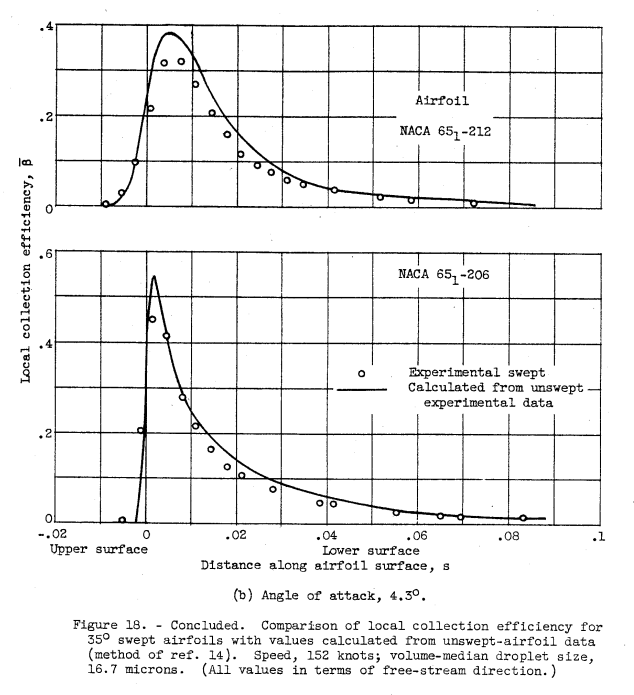
Reference 14 is NACA-TN-2931 4.
Conclusions
From NACA-TN-3839:
SUMMARY OF RESULTS
The impingement characteristics of several airfoils obtained experimentally using a dye-tracer technique yield the following results:
1. In general, the data show that the local and total water catch and the limit of impingement of airfoils are primary functions of the modified inertia parameter (in which airspeed and droplet and body size are the most significant variables) and airfoil thickness ratio. In addition, the local water collection rate and the extent of impingement on the airfoil surfaces depend on the airfoil angle of attack. Secondary factors affecting airfoil impingement characteristics are airfoil shape (for a given thickness ratio), small camber, and sweep angle.
2. With an increase in the modified inertia parameter, the total and local collection efficiencies and the impingement limits also increase. For those airfoils of a comparable series operating at a typical flight value of the modified inertia parameter, a thickness ratio of 6 percent had total collection efficiencies of 1.7 and 2 times those of a 12- and 15-percent-thick airfoil, respectively. Airfoils with relatively blunt leading edges (Joukowski 0015) had higher total collection efficiencies than those with sharp leading edges (low-drag airfoils such as the NACA 652-015), although the impingement limits for the sharper airfoils were greater than those for the blunt airfoils.
3. The experimentally determined local and total collection efficiencies and impingement limits for the Joukowski 0015 and NACA 652-015 airfoils are in good agreement with the theoretical values. No such agreement is obtained for the NACA 651-212 airfoil.
4. Over the range of conditions studied, the experimental data substantiate a previous method of predicting the impingement characteristics of swept airfoils (design section laid out perpendicular to the leading edge) from data for the unswept design section.
5. Because of the typical droplet-size distribution of the tunnel spray, and the correlation of data by means of the modified inertia parameter, the experimental results herein may be applied over a wide range of flight conditions.
Citations
From scholar.google.com:
NACA-TN-2931: 16 citations
NACA-TN-3839: 15 citations
Related
This is part of the Water Drop Impingement on Surfaces thread.
The method of NACA-TN-2931 for swept wings is still used today. The AIAA Ice Prediction Workshop, reference 11, has an example of use in conjunction with LEWICE2D (and frankly, LEWICE2D performed as well as any of the other methods in the workshop).
Notes
-
Gelder, Thomas F., Smyers, William H., Jr., and von Glahn, Uwe H.: Experimental Droplet Impingement on Several Two-Dimensional Airfoils with Thickness Ratios of 6 to 16 Percent. NACA-TN-3839, 1956. ntrs.nasa.gov ↩
-
Bergrun, Norman R.: A Method for Numerically Calculating the Area and Distribution of Water Impingement on the Leading Edge of an Airfoil in a Cloud. NACA-TN-1397, 1947. ntrs.nasa.gov ↩
-
Guibert, A. G., Janssen, E., and Robbins, W. M.: Determination of Rate, Area, and Distribution of Impingement of Waterdrops on Various Airfoils from Trajectories Obtained on the Differential Analyzer. NACA-RM-A905, 1949. digital.library.unt.edu ↩
-
Dorsch, Robert G., and Brun, Rinaldo J.: A Method for Determining Cloud-Droplet Impingement on Swept Wings. NACA-TN-2931, 1953. ntrs.nasa.gov ↩↩
-
Brun, Rinaldo J., Gallagher, Helen M., and Vogt, Dorothea E.: Impingement of Water Droplets on NACA 651-208 and 651-212 Airfoils at 4° Angle of Attack. NACA-TN-2952, 1953. ntrs.nasa.gov ↩
-
Brun, Rinaldo J., Gallagher, Helen M., and Vogt, Dorothea E.: Impingement of Water Droplets on NACA 65A004 Airfoil and Effect of Change in Airfoil Thickness from 12 to 4 Percent at 4° Angle of Attack. NACA-TN-3047, 1953. ntrs.nasa.gov ↩
-
Serafini, John S.: Impingement of Water Droplets on Wedges and Double-Wedge Airfoils at Supersonic Speeds. NACA-TR-1159, 1954. (Supersedes NACA-TN-2971.) ntrs.nasa.gov ↩
-
Brun, Rinaldo J., Gallagher, Helen M., and Vogt, Dorothea E.: Impingement of Water Droplets on NACA 65A004 Airfoil at 8° Angle of Attack. NACA-TN-3155, 1954. ntrs.nasa.gov ↩
-
Brun, Rinaldo J., and Vogt, Dorothea E.: Impingement of Water Droplets on NACA 65A004 Airfoil at 0° Angle of Attack. NACA-TN-3586, 1955. ntrs.nasa.gov ↩
-
Brun, Rinaldo J., and Vogt, Dorothea E.: Impingement of Cloud Droplets on 36_5-Percent-Thick Joukowski Airfoil at Zero Angle of Attack and Discussion of Use as Cloud Measuring Instrument in Dye-Tracer Technique. NACA-TN-4035, 1957. ntrs.nasa.gov ↩
-
AIAA Ice Prediction Workshop, 1st Workshop, Day 1 presentations, Cook_Boeing_Presention, icepredictionworkshop.wordpress.com ↩