"the ideal flow field ahead of a ribbon is not a very satisfactory representation of the actual flow field in front of a rectangular body"
NACA-TN-3658, "Impingement of Water Droplets on a Rectangular Half Body in a Two-Dimensional Incompressible Flow Field" 1
Summary
Water-drop impingement on a rectangular body is calculated.
Abstract
Trajectories of water droplets moving in the ideal two-dimensional flow field ahead of a body of rectangular cross section and infinite extent in the downstream direction have, been calculated by means of a differential analyzer. Data on collection efficiency and distribution of water impingement are presented.
Discussion
We have already seen most of the titles on the "Impingement on Other Surfaces" topic:
- Brun, Rinaldo J., and Mergler, Harry W.: Impingement of Water Droplets on a Cylinder in an Incompressible Flow Field and Evaluation of Rotating Multicylinder Method for Measurement of Droplet-Size Distribution, Volume-Median Droplet Size, and Liquid-Water Content in Clouds. NACA-TN-2904, 1953. ntrs.nasa.gov
> previous review: NACA-TN-2904 - Brun, Rinaldo J., Serafini, John S., and Gallagher, Helen M.: Impingement of Cloud Droplets on Aerodynamic Bodies as Affected by Compressibility of Air Flow Around the Body. NACA-TN-2903, 1953. ntrs.nasa.gov
> previous review: NACA-TN-2903 - von Glahn, Uwe H., Gelder, Thomas F., and Smyers, William H., Jr.: A Dye-Tracer Technique for Experimentally Obtaining Impingement Characteristics of Arbitrary Bodies and a Method for Determining Droplet Size Distribution. NACA-TN-3338, 1955. ntrs.nasa.gov
> previous review: NACA-TN-3338 - Brun, Rinaldo J., Lewis, William, Perkins, Porter J., and Serafini, John S.: Impingement of Cloud Droplets and Procedure for Measuring Liquid-Water Content and Droplet Sizes in Supercooled Clouds by Rotating Multicylinder Method. NACA-TR-1215, 1955. (Supersedes NACA TN’s 2903, 2904, and NACA-RM-E53D23) ntrs.nasa.gov
> previous review: NACA-TR-1215, NACA-TR-1215 Thermodynamics - von Glahn, Uwe H.: Use of Truncated Flapped Airfoils for Impingement and Icing Tests of Full-Scale Leading-Edge Sections. NACA-RM-E56E11, 1956. ntrs.nasa.gov
> previous review: Scaling in NACA tests
So, we will devote this review to the title that we have not yet seen, NACA-TN-3658.
Why would anyone studying aircraft icing care about impingement on a ribbon or rectangle? They seem to be a rather non-aerodynamic surfaces.
Among the general body shapes of interest is that of a rectangular body having a flat surface facing the airstream. Such a body may be used as an approximation to the shape of the sensing elements of certain instruments used to measure icing-cloud properties.
Cloud-droplet size and size distribution are sometimes measured by collecting samples of cloud droplets on small transparent slides coated with oil or some water-sensitive substance (refs. 6 to 8). The slides are then photographed to obtain a record of the droplet size distribution. Various types of sampling devices have been used in which the collecting element is usually a flat surface perpendicular to the airstream. The evaluation of the cloud-droplet size distribution from samples obtained in this way requires a knowledge of the relation between droplet diameter and collection efficiency. Droplet-impingement data applicable to a body of rectangular cross section would also be useful in estimating the collection efficiency of the central portion of the rotating-disk icing-rate meter (refs. 7 to 9) and the rectangular bars used to measure the spray distribution in an icing wind tunnel (ref. 10).
In the Icing on Cylinders thread, we saw NACA-TN-3338, which includes Figure 10:
A square grid made up of 1/8- by 1/2- by 24-inch bar stock held ribbons which were used for measuring cloud uniformity and was mounted in the tunnel test section as shown in figure 10.
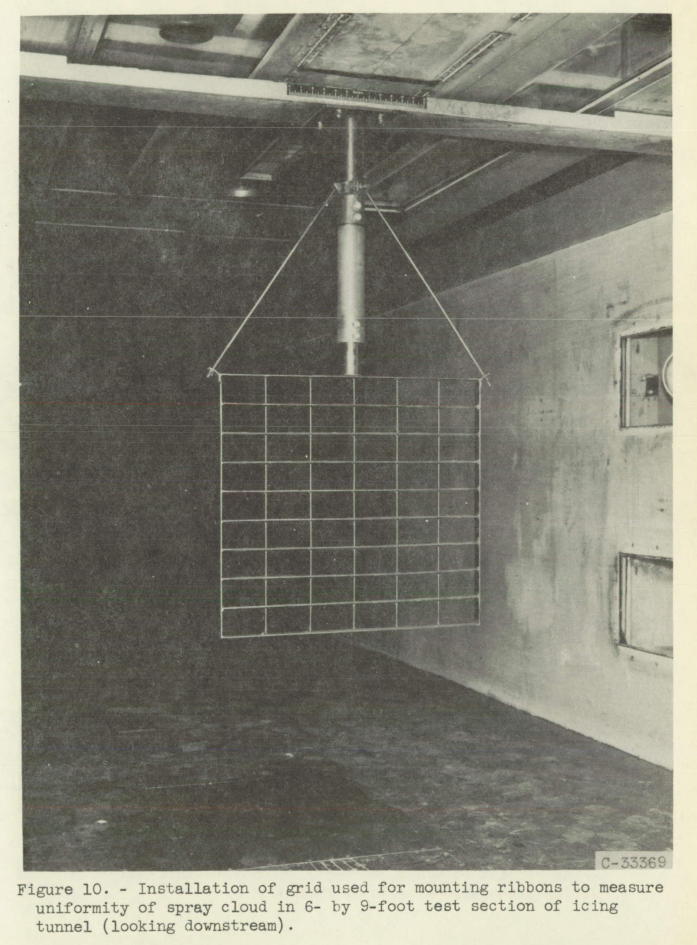
Similar grids are still used today in the calibration of icing wind tunnels.
We saw the rotating disk icing rate meter in NACA-RM-A9C09 Instruments. This may be approximated as a ribbon with height equal to the disk thickness.
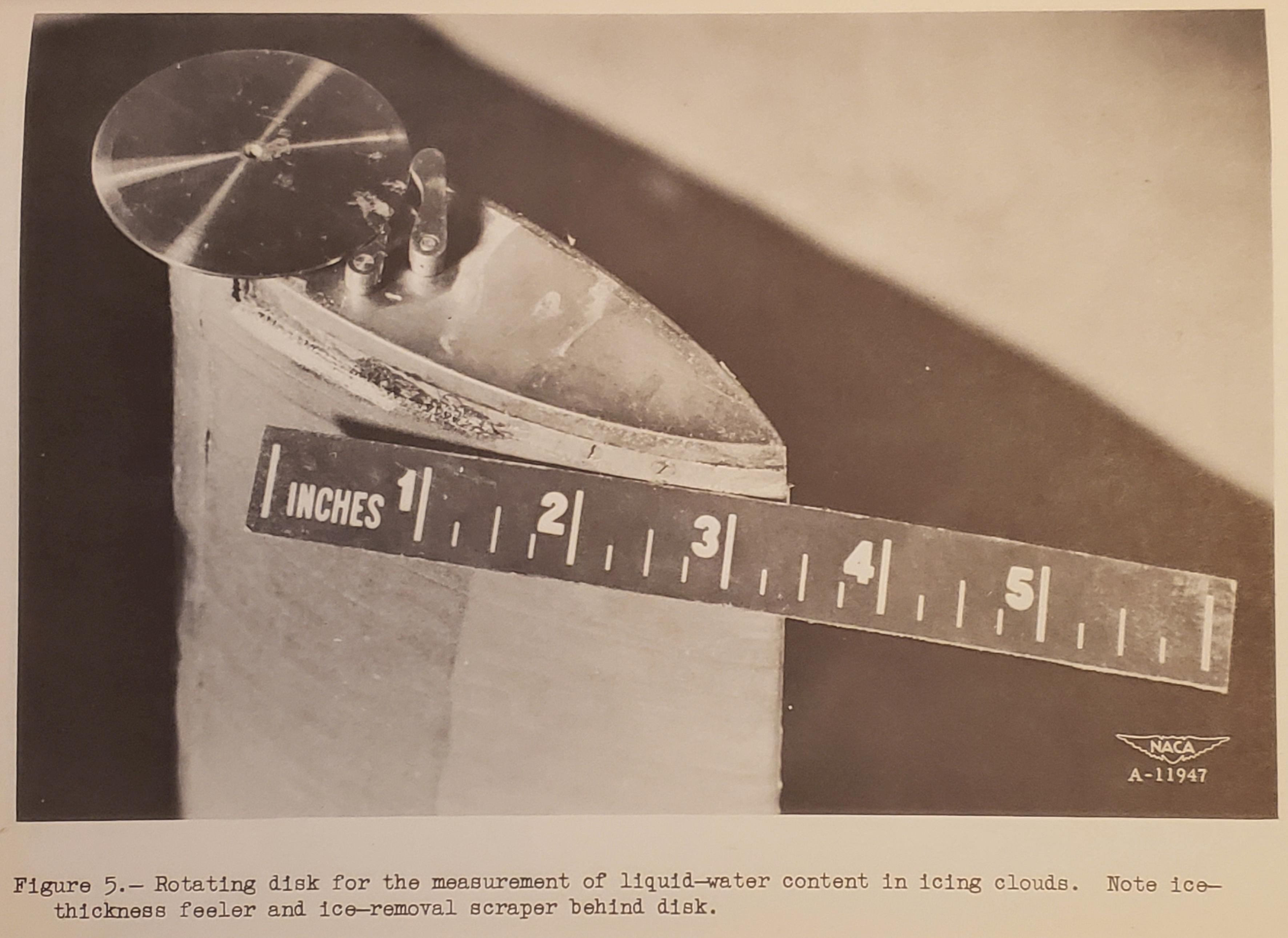 Figure 5 of NACA-RM-A9C09. Rotating disk for the measurement of liquid-water content in icing clouds.
Comparisons to the ribbon analysis from Mathematical Investigation of Water Droplet Trajectories
Trajectory calculations based on ideal two-dimensional flow about a ribbon (ref. 11), which is essentially a rectangle of zero chord, have been used as an approximation to obtain the impingement on rectangular bodies of finite chord. However, the ideal flow field ahead of a ribbon is not a very satisfactory representation of the actual flow field in front of a rectangular body because of the dependence of the flow ahead of the body on conditions existing behind the body.
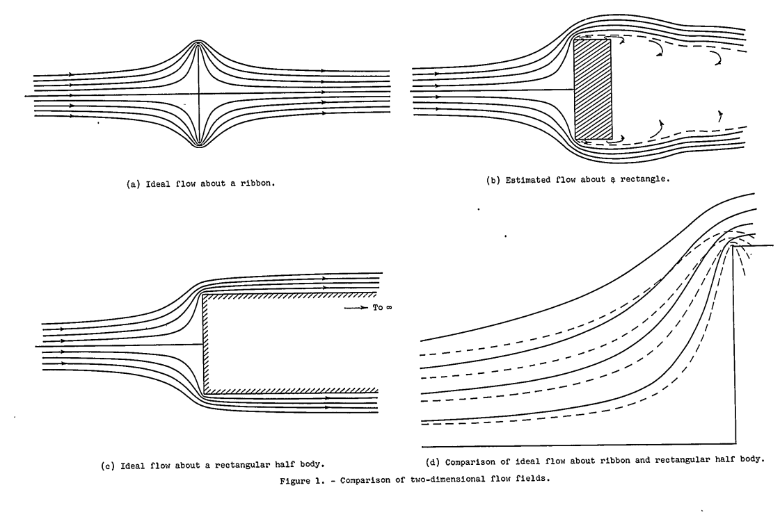
The ideal flow field about a ribbon is symmetrical fore and aft, as shown in figure 1(a), with the streamlines closing in directly behind the body. In the case of real flow about a rectangular body, on the other hand, the streamlines cannot be calculated exactly; but general knowledge of the flow about solid boundaries suggests that the flow field is something like that shown schematically in figure 1(b). Flow separation occurs at the edge, and a wake is formed extending downstream. The effect of variations in the ratio of chord to thickness cannot be estimated accurately, but is probably small, since the wake is roughly equivalent to an indefinite downstream extension of the body.
Potential flow exists outside the limits of the boundary layer and wake (shown approximately by the dashed line). Figure 1(c) shows the ideal-flow streamlines around a rectangular half body (a body of infinite extent downstream). This flow field resembles the estimated real flow in figure 1(b) much more closely than does the ideal flow about a ribbon (fig. 1(a)). The effect of the downstream extent of the body on the flow field ahead is shown in figure 1(d), which is a superposition of portions of the fields shown in figures 1(a) and (c). The comparison shows that the presence of the afterbody exerts a considerable influence on the flow field ahead of the body.
The ideal flow field of the rectangular half body represents a closer approximation to real flow than does the ideal flow about a ribbon; however, it too is subject to the disadvantage that the velocity becomes infinite at the corner. In spite of this disadvantage, the ideal flow field in front of the rectangular half body was used, in the calculation of trajectories, because It was considered to be sufficiently realistic to yield approximate results of practical value and because the velocity components could be calculated without too much difficulty.
Reference 11 is Mathematical Investigation of Water Droplet Trajectories.
Differential Equations of Droplet Motion
The differential equations that describe the motion of the droplets were obtained by equating the drag force with the rate of change of momentum of the droplet (ref. 4). The equations are expressed in dimensionless form in order to maintain the number of calculations at a minimum and to simplify the presentation of the results. They apply to the motion of droplets in a plane perpendicular to the edges of the rectangular half body in the system of rectangular coordinates shown in figure 2.
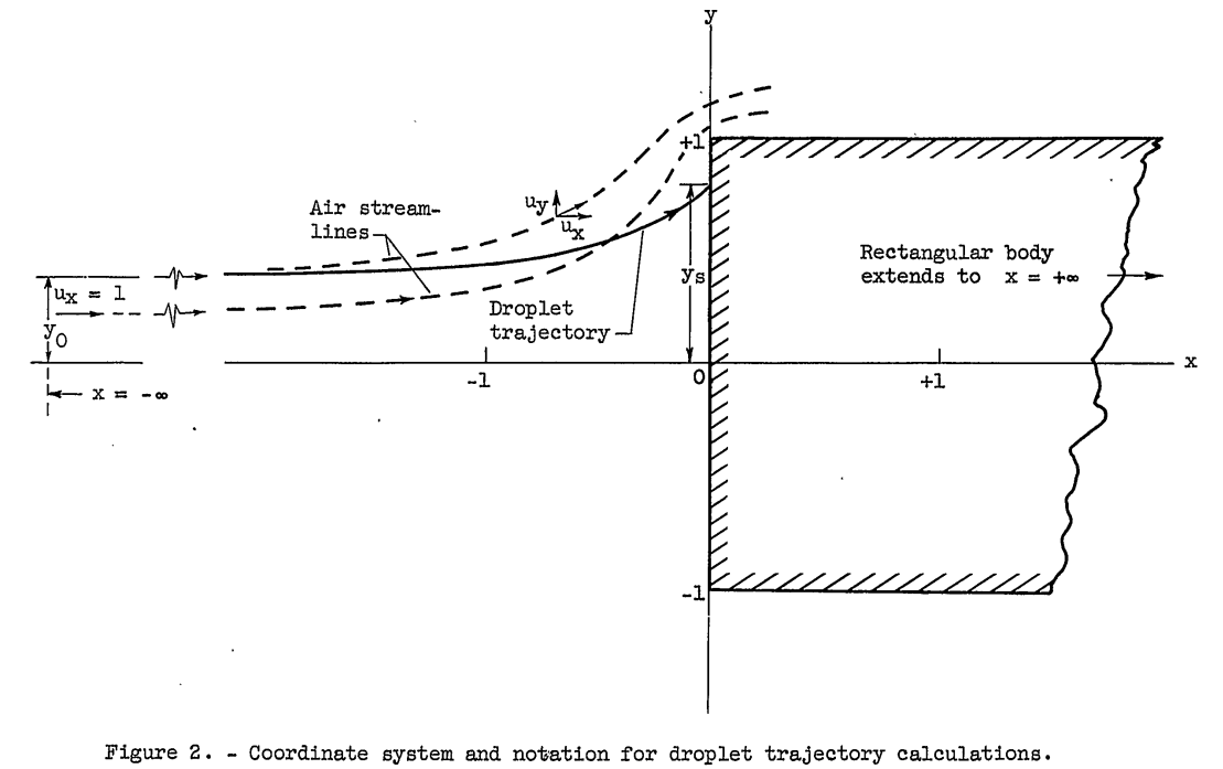
Reference 4 is NACA-TN-2904.
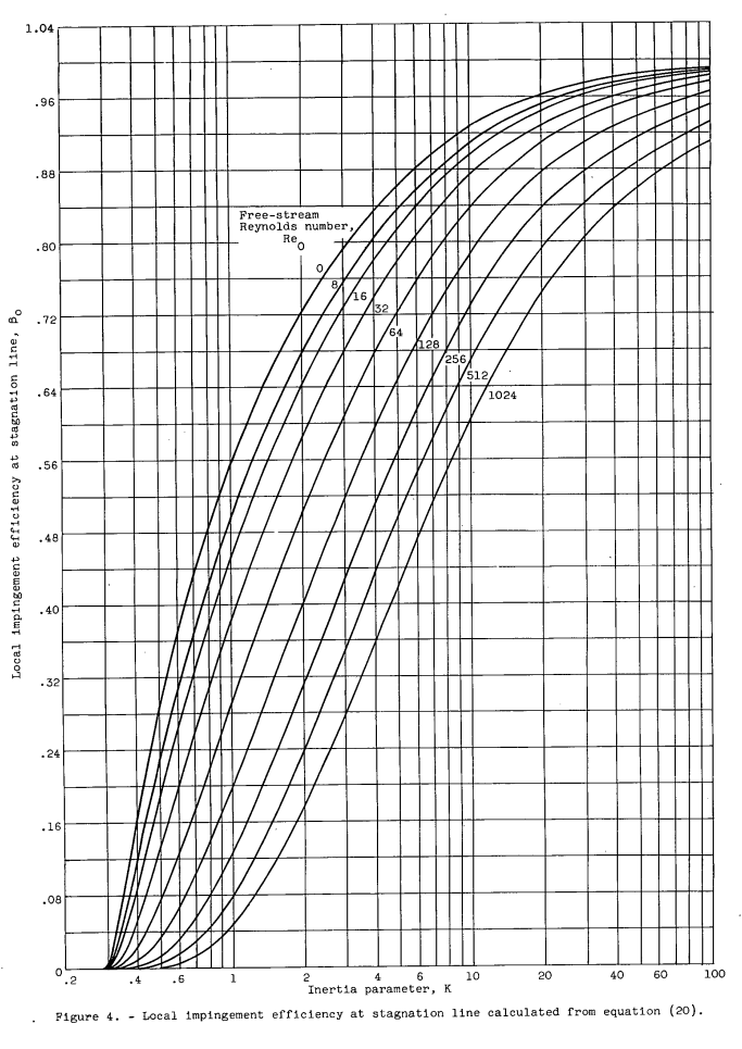
Values of n, β0 and E calculated from the empirical equations are presented in figures 3, 4, and 5, respectively. The 74 values of YO obtained with the differential analyzer and the corresponding values calculated from the equations are presented for comparison in table II. The standard deviation of the differences between corresponding values is 0.0051; therefore, the probable error involved in using the equations to determine y0 is ±0.0034 based on the assumption that the results from the trajectories are absolutely correct. The dimensionless parameters Re0 and K are defined in equations (3) and (4). Equations and graphs for use in determining values of K and Re_0 in terms of air speed, altitude, body size, and droplet diameter in practical units are presented in reference 13.
In the end, the difference between the ribbon and the semi-infinite rectangle are small.
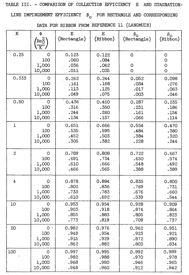
It was pointed out in the discussion of flow fields in the INTRODUCTION that the flow field of the rectangular half body differs from that of the ribbon by the addition of an afterbody, but that both differ from the real flow about a rectangular body because of the absence of flow separation and because of the requirement of infinite velocity at the edges. An examination of the comparative streamlines in figure 1(d) shows a great difference in velocity in the immediate vicinity of the edge. (Velocity is inversely proportional to streamline spacing.) In spite of the difference in the flow fields, however, the differences in collection efficiency of the ribbon and rectangle are only moderate. The maximum difference in table III is 0.099 at K = 2 and φ = 10,000, and the average difference for all values in table III is 0.026. These facts suggest that-the results obtained using the ideal flow ahead of the rectangular half body are likely to be a fairly good approximation to the actual impingement on a rectangular body in real flow. The largest difference between the ideal flow and the real flow is that the ideal flow permits a high local air velocity in the neighborhood of the edge; however, these differences in local air velocity in the neighborhood of the edge have a relatively small effect on the trajectories.
Conclusions
CONCLUDING REMARKS
The rate and distribution of water impingement on a semi-infinite rectangular body moving in a cloud of uniform liquid-water content and droplet size have been determined by means of droplet trajectory calculations. Empirical equations have been found providing an approximate representation of the impingement rate and distribution in terms of the inertia parameter K and the free-stream droplet Reynolds number Re_0 Equation (17) gives the local impingement efficiency 13 as a function of distance from the centerline of the rectangle in terms of the following three parameters: (1) the collection efficiency E, (2) the impingement efficiency at the centerline β0, and (3) the impingement distribution index n.
These parameters may be determined from K and Re_0 by means of empirical equations (19), (20), and (21).
Citations
From scholar.google.com:
NACA-TN-3658: 14 citations
Related
This is part of the Water Drop Impingement on Surfaces thread.
Notes
-
Lewis, William, and Brun, Rinaldo J.: Impingement of Water Droplets on a Rectangular Half Body in a Two-Dimensional Incompressible Flow Field. NACA-TN-3658, 1956. ntrs.nasa.gov ↩