"I am surprised to find that there are so many details which have not been anticipated before the de-icing tests were started." (1942)
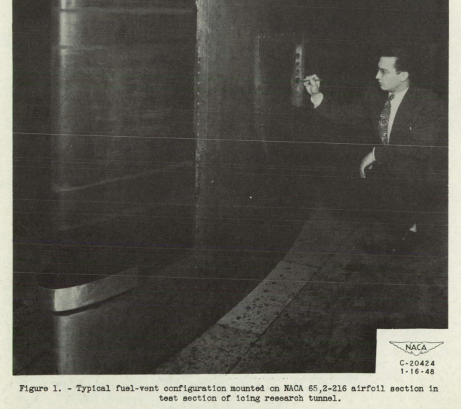
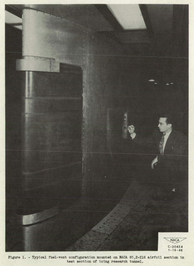
Figure 1 from NACA-TN-1789.
Summary
The effects of icing on small components must be addressed.
Key points
- Flight tests in natural icing revealed (and still reveal) small component icing effects.
- Fuel vents designs were evaluated.
- "At present very little is known of the effect of radome icing on radar operation."
- The effect of icing on the radome for radar was evaluated.
Introduction
We saw some details of the Lewis Rodert's work on the Lockheed 12A test aircraft in Engine Exhaust Heat. However, wing ice protection was not the only challenge:
To fly into ice clouds and survive, the Ames group necessarily became expert on the impact of ice on the total aircraft. "I am surprised to find", noted [NACA Langley] Engineer-in-Chief Smith DeFrance, "that there are so many details which have not been anticipated before the de-icing tests were started." Frosting prevented photographs out cabin windows; Clousing and McAvoy found they needed better instruction on flying blind; electrically-heated pitots looked clean even when ice in the throat skewed pressure readings; exhaust gas corroded the aluminum alloy at the wing tip; and the radio broke regularly. Rodert persuaded United Airlines to install in the 12A a radio they had specially adapted to ice flying. He asked the Massachusetts Institute of Technology (MIT) to design electric-resistance heating for the twenty-five foot-long antenna wire that stretched between the cabin and the tail. And he asked the Naval Research Laboratory and the Air Corps labs at Wright Field to design loop antennas that would not collect static as they encountered precipitation. Any sharp corner or gadget protruding into the airstream, Rodert constantly reminded manufacturers, was an invitation both to icing and static electricity.
Reported in "Lew Rodert, Epistemological Liaison, and Thermal De-Icing at Ames". 1
Safe flight in icing conditions requires design for "the impact of ice on the total aircraft", as noted above, not just the larger components that we have seen most of so far (wings and engines).
We previously looked at windshield ice protection. Here, we will look at NACA publications on two other airplane components, fuel vents and radomes.
"Investigation of Aerodynamic and Icing Characteristics of Recessed Fuel-Vent Configurations", NACA-TN-1789 2
"this location of the vents is in an area susceptible to icing"
An investigation has been conducted in the NACA Cleveland icing research tunnel to determine the aerodynamic and icing characteristics of several recessed fuel-vent configurations. The vents were investigated aerodynamically to obtain vent-tube pressures and pressure distributions on the ramp surface as functions of tunnel-air velocity arid. angle of attack. Icing Investigations were made to determine the vent-tube pressure losses for several icing conditions at tunnel-air velocities ranging from 220 to 440 feet per second.
...
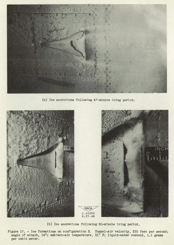
In a cloud-icing condition, roughness caused by ice formations on the airfoil surface ahead of the vent ramp, rather than icing of the vent configuration, caused a rapid loss in vent-tube pressures during the first few minutes of an icing period. Only the configuration having diverging ramp sidewalls, a 7 ramp angle, and a common plenum chamber maintained the required vent-tube pressures throughout a 60-minute icing period, although the ice formations on this configuration were more severe than those observed for the other configurations. No complete closure of vent-tube openings occurred for the configurations investigated.
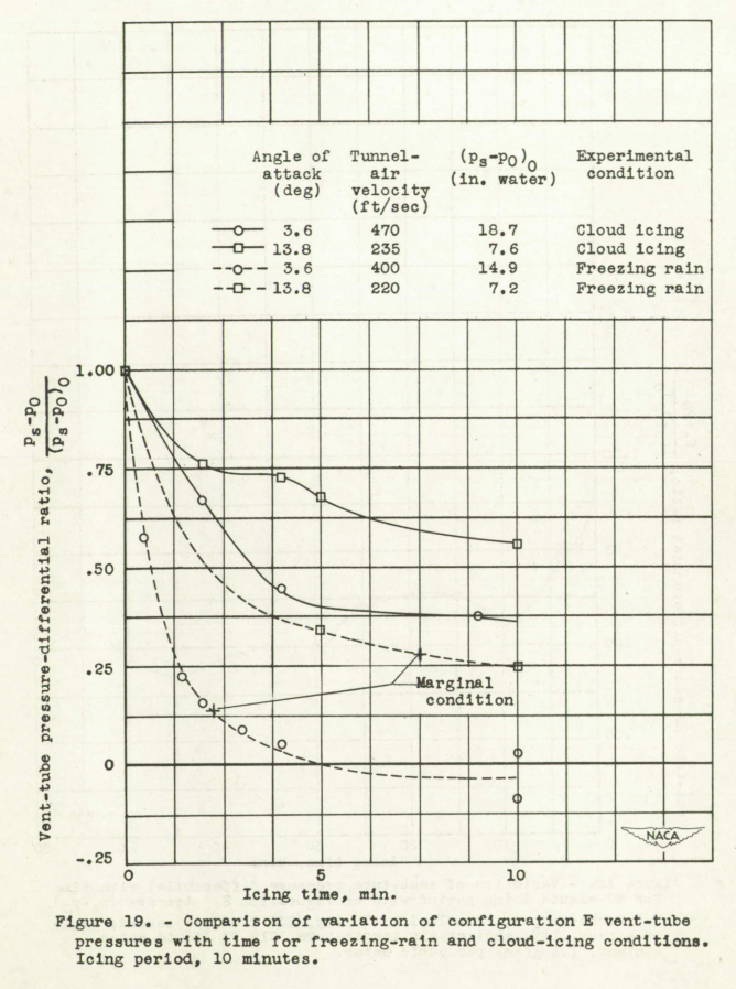
A simulated freezing-rain condition caused a greater and more rapid vent-tube pressure loss than was observed for a cloud-icing condition.
[Note: a "fuel cell" below is a type of fuel tank or sub-tank, not an electricity generating technology.]
Introduction
Several types of fuel cell now in use in transport airplanes tend to collapse under negative pressure, venting in such a manner that much of the contents is expelled. Overpumping during fuel transfer between cells may also cause the fuel to be expelled through the vents. The location of fuel-cell vents is very important in the reduction of fire hazards because fuel expelled from improperly located vents may seep into the wings or the fuselage proper and thereby create a serious fire hazard. The existence of a negative pressure in a fuel coil may be eliminated by proper sealing of the fuel-cell compartment and by venting the compartment to the upper wing surface while venting the fuel cell to the lower surface. This solution, however, is impractical for many existing fuel-cell installations because of structural difficulties.
In order to minimize the fire hazard, the vents can be relocated from the fuselage and the nacelles to the lower surface of the outer wing panels. Because this location of the vents is in an area susceptible to icing, particularly during high angle-of-attack attitudes, it was necessary to determine whether ice formations would sufficiently impair the aerodynamic characteristics of the vent to cause failure of the fuel cells.SUMMARY OF RESULTS
...
Icing
4. Rapid losses in vent-tube pressures during the first few minutes in icing conditions were caused by the roughness of the ice formations on the airfoil surface ahead of the vent ramp rather than by the icing of the vent configuration.
5. In similar cloud-icing conditions, only the configuration in which the highest vent-tube pressures were attained maintained the required vent-tube pressure throughout a 60-minute icing period. In general, the configurations with diverging ramp walls maintained adequate vent-tube pressures for a longer period of time in an icing condition than configurations with parallel ramp walls.
6. For similar cloud-icing conditions, the ice formations on the rear wall slope for configurations with diverging ramp walls were more severe than those observed for configurations with parallel walls. These more severe ice formations, however, did not appreciably influence the vent-tube pressures.
7. At an angle of attack of 14° and at a tunnel-air velocity of 240 feet per second, no complete closure of vent-tube openings duo to ice formations occurred for the configurations investigated, although the areas of the vent-tube openings and the plenum-chamber entrance were considerably reduced in some instances by ice formations.
8. For simulated freezing-rain conditions, the vent-tube pressure losses for all configurations were greater and occurred more rapidly than those observed for a cloud-icing condition. These large and rapid vent-tube pressure losses were more detrimental at the smaller angles of attack because the marginal pressure values were reached in a matter of minutes.
9. Negative vent-tube pressures were realized in some instances for both cloud-icing and simulated freezing-rain conditions. For the configuration having the highest vent-tube pressure characteristics, negative pressure values were obtained, only at low angles of attack in a freezing-rain condition.
"Experimental Investigation of Radome Icing and Icing Protection", NACA-RM-E52J31 3
"At present very little is known of the effect of radome icing on radar operation."
SUMMARY
An investigation has been conducted in the NACA Lewis icing research tunnel to determine the icing characteristics, the effects of icing on radar operation, and the protection requirements for two radome configurations. The radomes were for the F-89 airplane and were investigated at airspeeds up to 290 miles per hour, air total temperatures from -15° to +20° F, water contents up to 1.0 gram per cubic meter, and angles of attack of 0° and 4°. A fluid protection system using ethylene glycol was used for both anti-icing and de-icing.
The impingement of water and formation of ice on the radomes were found to agree well with theory and experience. The ice formations were found to produce serious effects on the radar performance. The fluid protection system gave adequate icing protection with anti-icing and de-icing requirements of practical magnitude.
INTRODUCTION
In modern all-weather aircraft, radar has become of increasing importance in assuring successful performance of the airplane in all atmospheric and operational conditions. This is particularly true of military aircraft, where, in addition to its use as a landing and navigational aid, radar is used for bomb sighting, target tracking, and gunfire control. Successful operation of modern aircraft demands, therefore, unimpeded radar operation.
...
At present very little is known of the effect of radome icing on radar operation. Theoretical calculations of the transmission of microwaves through ice can be made but are dependent upon the values assumed for the electrical properties of ice. Reference 1 indicates considerable variation in both the dielectric constant and conductivity for bulk ice produced in the laboratory. In addition, it is known that ice formations encountered in flight are considerably different in type and structure from bulk ice. Flight radome icing very probably would also differ in type and structure from ice produced on a radome in static conditions as in a cold chamber. It would appear, therefore, that neither calculations nor static tests will give realistic values of the effect of radome icing on radar performance.
...
Two radome configurations were tested, those for the F-89C and F-89D airplanes employing APG-33 and APG-40 radar, respectively. The radar is of the conical-scan type with a parabolic reflector-type antenna. The radar is mounted in the nose of the airplane; the radomes are bodies of revolution which fair into the nose of the fuselage. Sketches showing sectional views of the two radome configurations are presented in figure 1.
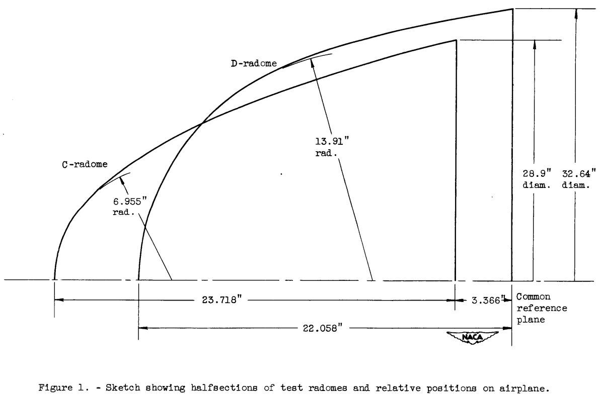
The narrow C-radome is essentially parabolic in section having a nose radius of 6.955 inches. The blunt D-radome is almost hemispherical, with a nose radius twice that of the C-radome, or 13.91 inches. Figure 1 also shows the location of the two radomes relative to a common reference plane on the airplane. Both radomes were of similar construction, consisting of molded Fiberglas impregnated with a synthetic resin; the nominal thickness of both radomes was 3/8 inch. The outer surfaces of the radomes were coated with Gayco, a rubber-like material, to resist erosion and abrasion.
The radar operates in the X--band (3.2 cm wavelength) with nominal frequencies of 9245 and 9375 megacycles for the C- and D-radomes, respectively. The operation of this type of radar can best be seen by reference to figures 2 and 3. The radar feed which projects ahead of the parabolic antenna directs the microwave signal towards the antenna, which reflects the electromagnetic beam forward. Since the feed is rectangular, a beam which is elliptical in cross section is obtained. The antenna nutates about a spin axis and is also set at an angle with respect to the spin axis as shown in figure 2. The radar beam is thus made to follow a wobble motion; the center of the beam describes the surface of a cone in space. In addition, the antenna moves or scans with respect to the radome axis in both the azimuth and elevation planes. Space limitations restricted the scan angle to ±30° and ±35° on the C- and D-radomes, respectively. Any object that falls within the beam during a nutation of the antenna will return a series of echos that are amplitude-modulated
as the antenna rotates. The modulated signal can then be used to indicate the angular displacement of the line of sight from the antenna to the object relative to the radome axis.
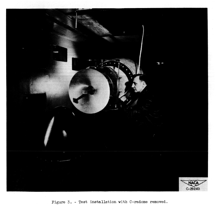
The antenna and necessary electronic equipment together with the test radomes were mounted on a faired afterbody installed in the test section of the icing research tunnel. A view of the setup with the C-radome removed showing the antenna is shown in figure 3.
Droplet impingement and icing.
The determination of the rate and location of the water-droplet impingement was accomplished by a tracer technique. Small amounts of a water-soluble dye (Azo Rubine) were placed in the icing-cloud spray water which was injected into the tunnel air stream ahead of the test section at air temperatures above freezing. Strips of an absorbent paper were wrapped around the radome surface upon which the water-dye solution impinged during the short (1 to 10 sec) exposure period. The liquid-water content of the cloud during these short exposures was obtained by exposing a narrow strip of the absorbent paper having a high and known collection efficiency. The quantity of dye collected on the absorbent paper was determined by means of a spectrophotometer, which together with the known dye concentration in the spray cloud yielded the local rate of deposition of water on the radome and the local collection efficiency. Impingement results were obtained for both the C- and D-radomes at airspeeds of approximately 175 and 290 miles per hour, angles of attack of 0° and 4°, liquid-water contents of 0.4 and 1.14 grams per cubic meter, and mean effective droplet diameters of 9 to 14 microns.
See airfoil impingement drop distribution for more on the dye tracer technique.
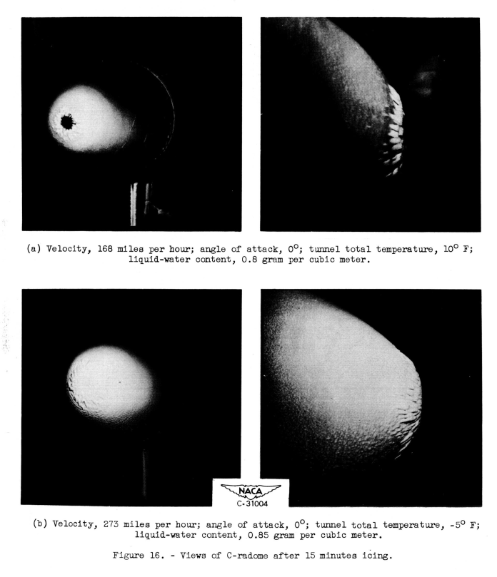
The photographs of figure 16 indicate that the main ice formation on the C-radome is confined to a rather narrow region near the radome nose. These main formations extend rearward a distance of 6 to 8 inches and are followed by a very light frost-like formation that extends to the rear of the radome.
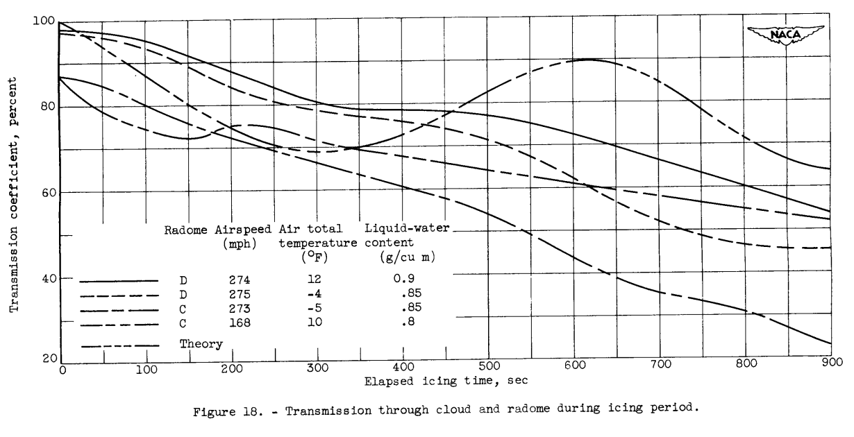
Transmission measurements were made during the 15-minute period in which the radomes were iced. These results a represented in figure 18 for the two radomes at zero scan angle and zero angle of attack. A theoretical curve has also been plotted for comparison with the experimental values. This theoretical curve was computed from the equations of reference 4 for normal one-way transmission through a flat plate of ice increasing in thickness at the rate of 2 inches per hour. A dielectric constant for ice of 3.3 and a loss factor of 1.66x10⁻⁶ (defined as electrical conductivity of material divided by product of frequency and dielectric constant) were assumed. All the experimental curves tend to oscillate as does the theoretical curve; this effect is more pronounced for the D- than for the C-radome. This result should be expected, since, as the ice thickness increases in multiples of the wavelength, alternate reinforcing and cancellation effects will occur as the wave is reflected in its passage through the ice layer.
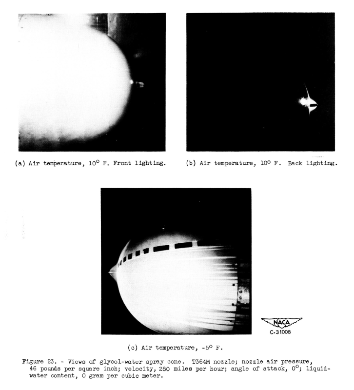
Views of the spray cone and flow of fluid on the radome surface produced by the T364M nozzle are shown in figure 23. The two views of figure 23(a) and 23(b) show the spray cone with an excess flow of fluid on the radome surface. The glycol flow rate is approximately 2 gallons per hour with no cloud-water spray. Reducing the flow rate slightly produces the partially wetted surface of figure 23(e), although the full spray cone is maintained. Further reductions in the glycol flow rate result in less of the radome being wetted with the flow in the form of streaks or rivulets. Eventually a point is reached at which the spray cone breaks down, and the fluid flows back over the nozzle and produces a very uneven distribution on the radome.
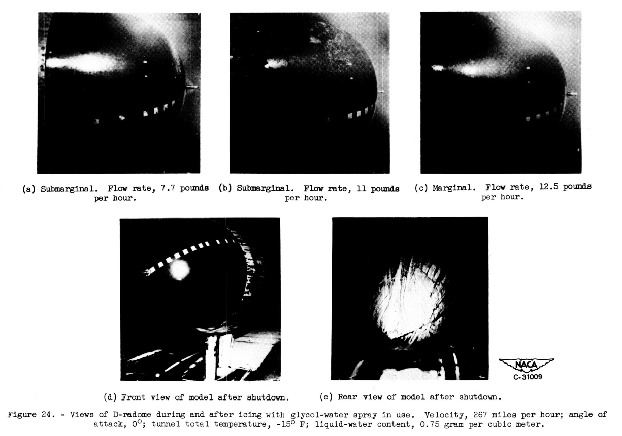
The photographs of figure 24 show some typical results of anti-icing on the D-radome with the T364M nozzle. In figure 24(a) insufficient fluid is supplied and the ice is building up on the front of the radome. Increasing the flow rate to 11 pounds per hour (fig.24(b)) eliminates the ice at the radome nose, but large slush-like formations appear at the rear of the radome. At a flow rate of 12.5 pounds per hour (fig.24(c)), the radome is entirely free from ice, although runback icing of a slush type occurs on the afterbody. Figures 24(c) and 24(d) show the fluid and runback ice formations remaining on the afterbody after the 34 minute test run. The large amounts of fluid and ice on the afterbody indicate the possibility of obscuring the aircraft windshield with this type of system.
Conclusions
Sometimes, a component can still function without ice protection. For current aircraft, many fuel vents and radomes do not have ice protection. However, to have an all-weather aircraft, one must do the tests to show that the results in icing conditions are acceptable.
For weather radar, different frequencies have different effects than those in this study. The attenuation for ice on the radome may be tolerable. However, other effects, such as ice shedding from the radome and the aerodynamic effects on air data probes down stream need to be addressed.
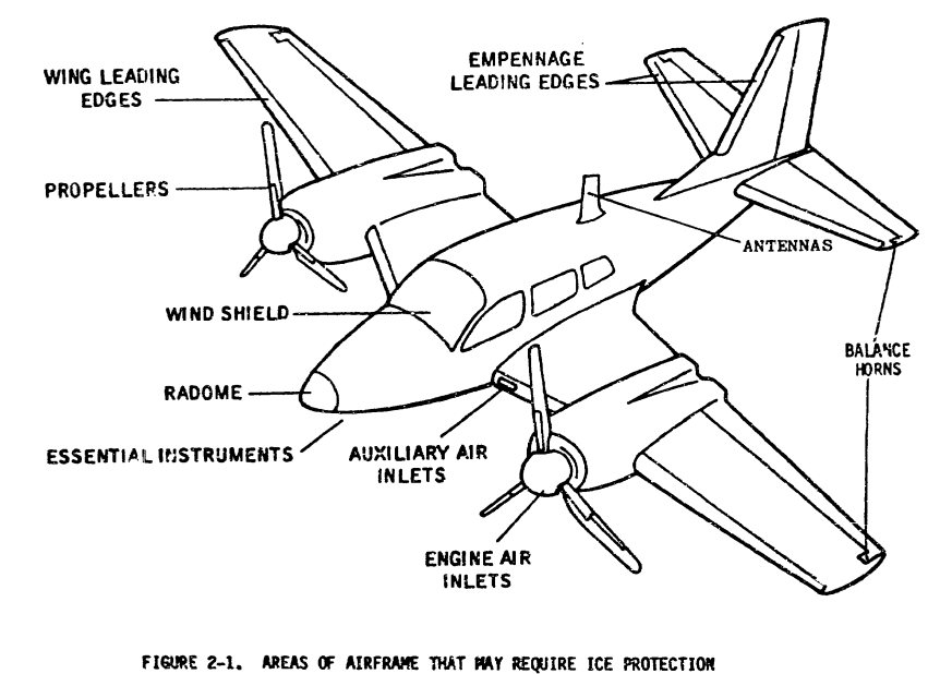
The FAA Aircraft Icing Handbook 4 recommends areas that may need ice protection. It does not list the numerous small components that might cause problems on some aircraft (but not others) if ice protection is not provided. "Any sharp corner or gadget protruding into the airstream" is not a bad description, although I might add gaps and holes to the list. It is up to you to show on your aircraft that they are not a problem. And I know that "discoveries" are still sometimes made about the adequacy of components for a particular aircraft on icing flight tests.
 From Aircraft Icing Handbook, Volume 2 4
See also
- Rodert, Lewis A: "The Effects of Aerodynamic Heating on Ice Formations on Airplane Propellers", NACA-TN-799, 1941. ntrs.nasa.gov
- Lewis, James P.: Wind-Tunnel Investigation of Icing of an Engine Cooling-Fan Installation. NACA-TN-1246, 1947. ntrs.nasa.gov
- Kepple, W. L.: Determination of Aircraft Antenna Loads Produced by Natural Icing Conditions. NACA-RM-E7H26a, 1948. ntrs.nasa.gov
- Gowan, W. H., Jr.: Vibration and Investigation of CAA Type V-I09 Very-High-Frequency Aircraft Antenna. NACA-RM-SE9D20. 1949. ntrs.nasa.gov
- Lewis, James P.: Investigation of Aerodynamic and Icing Characteristics of Flush Alternate-Inlet Induction-Systems Air Scoop. NACA-RM-E53E07, 1953. ntrs.nasa.gov
Citations
An online search (scholar.google.com) found citations for
NACA-TN-1789 3 times, and
NACA-RM-E52J31 6 times.
Notes
-
Mack, Pamela E.: From engineering science to big science: the NACA and NASA Collier Trophy research project winners. No. NASA/SP-1998-4219. 1998. Chapter 2. Lew Rodert, Epistemological Liaison, and Thermal De-Icing at Ames. ↩
-
Ruggeri, Robert S., von Glahn, Uwe H., and Rollin, Vern G.: Investigation of Aerodynamic and Icing Characteristics of Recessed Fuel-Vent Configurations. NACA-TN-1789, 1949. ntrs.nasa.gov ↩
-
Lewis,James P., and Blade, Robert J.: "Experimental Investigation of Radome Icing and Icing Protection", NACA-RM-E52J31, 1953. ntrs.nasa.gov ↩
-
"Aircraft Icing Handbook Volume 2", DOT/FAA/CT-88/8-2. apps.dtic.mil ↩↩