"an airplane that will be immune from the dangers of ice accumulation ... is only a matter of technical development." 1
Summary
Practical wing heating designs are developed and proven in natural icing flight tests.
Key Points
- Flight tests were used extensively, as icing wind tunnels were still under development.
- Much detailed development over 10 years was required.
- "Existing data indicate that sufficient heat is available... the problem is one of distribution".
- Design elements were developed that could be used in future compressed air heating.
Discussion
NACA-TR-403 1
This investigation was conducted by the National Advisory Committee for Aeronautics to study the practicability of employing heat as a means of preventing the formation of ice on airplane wings. The report relates essentially to technical problems regarding the extraction of heat from the exhaust gases and it proper distribution over the exposed surfaces. In this connection a separate study has been made to determine the variation of the coefficient of heat transmission along the chord of a Clark Y airfoil.
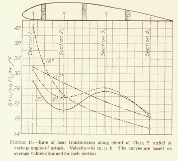
A study of the heat transmission from the airfoil reveals that the local transmission is very high at the leading edge and that it decreases rapidly to a minimum value at a point located about 30 per cent back along the chord. Experiments on ice prevention both in the laboratory and in flight show conclusively that it is necessary to heat only the front portion of the wing surface to effect complete prevention.
The marked variation in the heat transmission over the front portion of the wing makes the problem of an efficient heat-distributing system a matter of some technical difficulty. The actual quantity of heat needed for ice prevention is, however, surprisingly small, being in the order of one-tenth of that available in the engine exhaust gases. The relative merits of various methods of ice prevention by means of heat are analyzed with the result that a vapor system is found to offer the most satisfactory solution, especially for airplanes which are not constructed entirely of metal. In all-metal designs it may be entirely practicable to employ a direct exhaust-heating system.
Experiment in flight show that a vapor-heating system which extracts heat from the exhaust and distributes it to the wings is an entirely practical and efficient method for preventing ice formation.
A narrow slot on the upper surface located about one-tenth of the chord length from the leading edge is employed in these tests for the purpose of collecting the water which would otherwise blow back and freeze aft of the heated leading edge. The tests seem to indicate, however, that this slot may not be essential.
Wind tunnel tests were conducted with a cylinder and an airfoil section
to determine the rates of heat transmission.
(Thought we were done with Cylinders?)
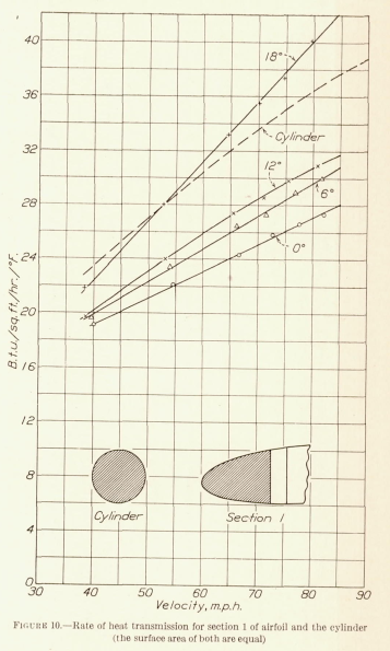
A study of the heat transmission from the airfoil reveals that the local transmission is very high at the leading edge and that it decreases rapidly to a minimum value at a point located about 30 per cent back along the chord.
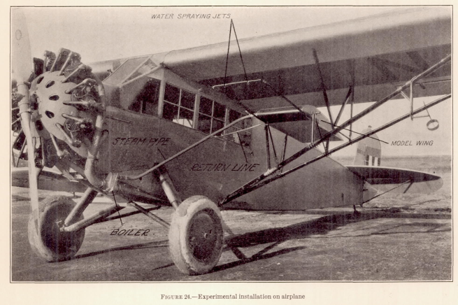
The model wing and the boiler were mounted on a Fairchild monoplane a shown in the photograph. (Fig. 24.) The boiler and the steam line were carefully insulated. The water return line runs from the drain cock on the lower left-hand corner of the leading edge down in to the main steam line and terminate at the bottom of the boiler in the manner indicated by the sketch in Figure 21. A steam pressure gauge facing the cabin is mounted on the upper part of the team pipe. This gauge was used to assist in checking the operation of the system while in flight.
For the purpose of reproducing atmospheric conditions artificially, a water-spraying system was included as part of the equipment. The spraying jets were mounted about 4 feet in front of the wing. The compressed air and water supply necessary for its operation were installed in the cabin.
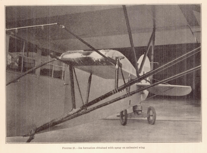
Unfortunately, owing to the weather conditions prevalent in this section of the country it has in only a few cases been possible to conduct full-scale tests under natural ice-forming conditions. In lieu of such tests, the spray system was employed. The spray produced drops which apparently varied in size from fine fog particles to light raindrops. The time of exposure of the droplets to the cold air was entirely too short to permit the extraction of much heat from the droplets. Consequently, all formations obtained were of the glaze ice type. Figure 25 is a photograph of a formation of ice obtained on the leading edge with the wing cold. The formation appears to be not unlike the glaze ice obtained on wings in natural ice storm. Notice the separate deposits from each of the two jets.
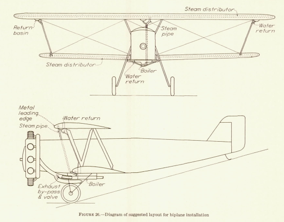
A full-scale design was proposed
(I do not know that it was ever built).
CONCLUSIONS
The most essential result obtained from this study is the fact that ample heat is available both in the exhaust and in the cooling water for the purpose of ice prevention.
An analysis of the possible methods for preventing ice formation showed that the employment of a vapor heating system (or of a direct exhaust-heating system in connection with all-metal airplane) offers the most convenient and promising solution.
The experiment showed that a vapor-heating system using a mixture of water and alcohol is an entirely practicable method, facilitating, in particular, the correct heat distribution to the wing surface. It was found that it is sufficient to heat only the front portion to prevent in fact the formation of ice on the entire wing.
It was found that the ice, which formed on the rear portion of a cloth-covered wing by water blowing back from the heated leading edge, was attached rather weakly to the surface and did not build up to any appreciable extent before it blew off.
The conclusion is drawn, however, that a small slot may be necessary on the upper surface behind the heated section to collect the rain water, particularly in connection with all-metal wing. The operation and efficiency of such slot have been carefully examined. It was found that the efficiency of the slot in collecting water is decreased greatly if its location is lesss than one-tenth of the chord length from the leading edge. A slot on the lower surface of the wing was found to be unnecessary.
It is believed that the high-wing monoplane will be the most convenient type for the incorporation of ice-prevention equipment based on the employment of engine waste heat. The successful design of an airplane that will be immune from the dangers of ice accumulation is, as far as can be judged from analysis and laboratory experiments, only a matter of technical development.
I do not know of an airplane that used the full-scale steam ice protection system, the model scale tests described here may be the only application.
The "... only a matter of technical development" took a decade, as we shall see.
NACA-TN-712 2
We saw some of NACA-TN-712 previously in the
Icing Wind Tunnel Thread.
Here, we will discuss the ice protection aspects.
SUMMARY An investigation was made in the N. A. C. A. ice tunnel at air temperatures from 20 to 28 F, and at a velocity of 80 miles per hour to determine whether ice formations on a model wing could be prevented by the use of the heat from the engine-exhaust gas. Various spanwise duct systems were tested in a 6-foot-chord N. A. C. A. 23012 wing model.
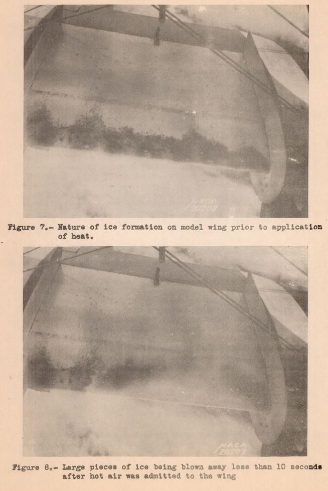
The formation of ice over the entire wing chord was prevented by the direct heating of the forward 10 percent of the wing by hot air, which was passed through leading-edge ducts.Existing data indicate that sufficient heat is available; the problem is therefore to determine how this heat can be utilized to the best advantage or, in other words, the problem is one of distribution.
TESTS AND RESULTS
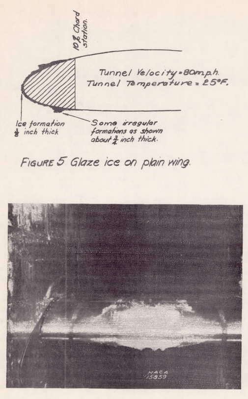
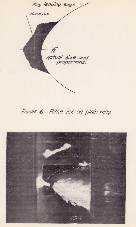
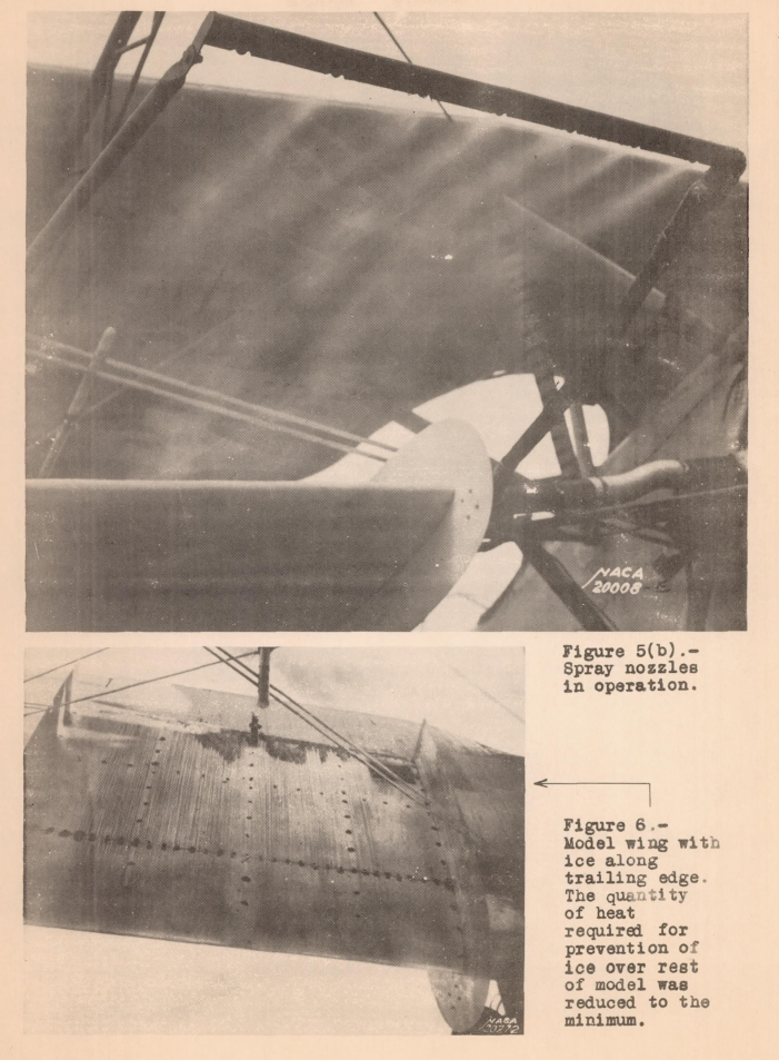
A photograph and a sketch shown in figure 5 illustrate a glaze-ice formation on the model. This formation is typical of ice encountered in precipitating clouds at temperatures about 28° F. The adjustment of the nozzle for this formation was such that large drops of water struck the model. Figure 6 illustrates a rime formation, which is typical of ice that would build up on a wing passing through a supercooled mist of very small waterdrops. The spray nozzle was adjusted so that only very small waterdrops struck the model. Rime ice formed only along or near a stagnation-pressure region. Other significant data are given on the sketches of figures 5 and 6.
CONCLUSIONS For the spray conditions existing during the tests, which produced typical ice formations at about 3 inches per hour, the following conclusions are drawn:
1. Ice formations over the wing of a 6-foot model were removed or prevented by a heating condition that would produce a skin temperature over the leading 10-percent portion of about 200 F. above tunnel air when the spray was not operating.
The gas temperature in the duct that was necessary to produce this skin temperature varied from 360 to 834 F. with corresponding air-duct velocities of 152 and 45 feet per second, respectively.
2. Ice formations at the leading edge were locally prevented by air that passed on the interior of the wing surface at a velocity of 30 feet per second and at a temperature of 122 F.
3. The heating requirements for the after portion of a wing chord are less stringent than at the leading edge because there it is only necessary to form a film of water between the ice and the wing to effect removal.
While NACA-TN-712 did not directly comment on the use of the icing wind tunnel, "We Freeze to Please": A History of NASA's Icing Research Tunnel and the Quest for Flight Safety notes that:
Although Rodert also used the icing tunnel to conduct experiments with electrically heated windscreen panels, he saw no future for tunnel-based research. He believed icing tunnels could not create conditions that resembled natural icing and far more could be accomplished with flight research.
As such, the next publication, NACA-TN-783, used flight tests for development.
NACA-TN-783 3
SUMMARY
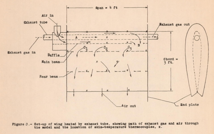
The National Advisory Committee for Aeronautics has conducted exhaust-heat de-icing tests in flight to provide data needed in the application of this method of ice prevention. The capacity to extract heat from the exhaust gas for de-icing purposes, the quantity of heat required, and other factors were examined. The results indicate that a wing-heating system employing a spanwise exhaust tube within the leading edge of the wing removed 30 to 35 percent of the heat from exhaust gas entering the wing. Data are given from which the heat required for ice prevention can be calculated. Sample calculations have been made on a basis of existing (engine power)/(wing area) ratios to show that sufficient heating can be obtained for ice protection on modern transport airplanes, provided that uniform distribution of heat can be secured.
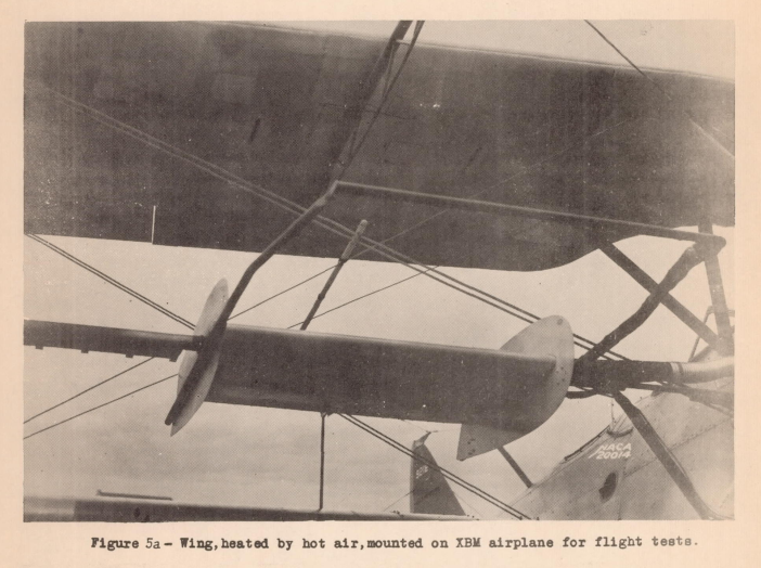
This publication has some excellent photos.
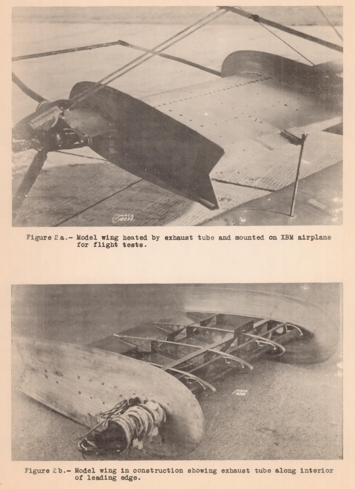
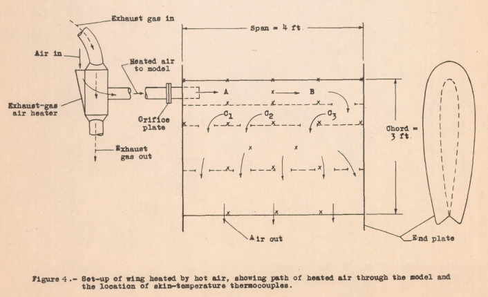
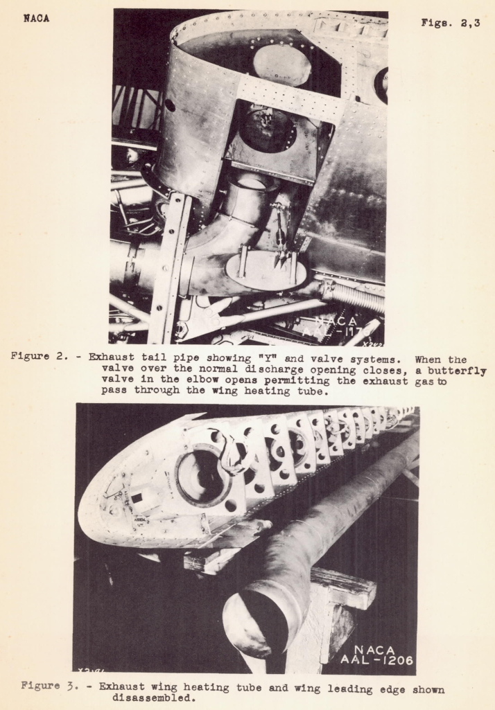
Two different means of providing the heat were considered (figures 3 and 4).
A water-spray system, similar to that in NACA-TR-403, was used in some cases to provide water drops.
CONCLUSIONS
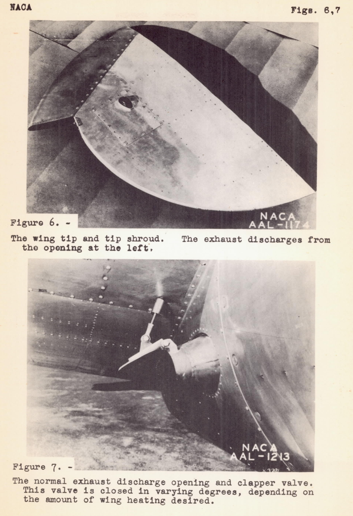
1. A wing with an exhaust-gas tube running spanwise inside of the leading edge provided a system capable of removing 30 to 35 percent of the heat from the exhaust gas entering the wing.
2. Heat transmission tests in misty cloud formations indicated that the heat required for ice prevention may be calculated from an equation involving the airplane speed and chord, and the ambient-air temperature.
Detailed design development
Several studies were conducted to develop details of the design.
- Rodert, Lewis A., and Jackson, Richard: Preliminary Investigation and Design of an Air-Heated Wing for Lockheed 12A Airplane. NACA-WR-A-34, April 1942. ntrs.nasa.gov
- Rodert, Lewis A. and Jackson, Richard: A Description of the Ju 88 Airplane Anti-Icing Equipment. NACA-WR-A-39 1942. ntrs.nasa.gov
- Jones, Alun R., and Rodert, Lewis A.: Development of Thermal Ice-Prevention Equipment for the B-17F Airplane. NACA-ARR-3H24, 1943. ntrs.nasa.gov
- Jones, Alun R., and Rodert, Lewis A.: Development of Thermal Ice-Prevention Equipment for the B-24D Airplane. NACA-WR-A-35, Feb. 1943. ntrs.nasa.gov
A Ju 88 airplane with exhaust heating was "obtained" by NACA in 1942 (I imagine there is more to the story that was left unsaid).
The overall design layout is similar to that used in NACA flight tests described below.
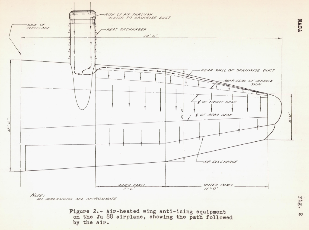
As a full-scale design had been implemented in 1941 by NACA, it does not appear that the Ju 88 design had direct influence on the NACA designs.
Full-Scale Flight Tests
"such tests should be conducted as soon as possible" NACA-TN-723, 1939
The "... only a matter of technical development" step advocated in NACA-TR-403 (1931) took a decade to achieve, but designs were now ready for full-scale airplane flight tests in natural icing conditions.
Three full-scale flight tests were performed on three different aircraft.
- NACA-ACR-A-53, Lockheed 12A, 1942.
- NACA-WR-A-7, B-24, 1943.
- NACA-ARR-4B02, B-17, 1944.
We will review one of those, NACA-ACR-A-53.
NACA-ACR-A-53 4
This publication has many excellent photos.
SUMMARY
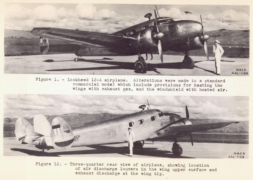
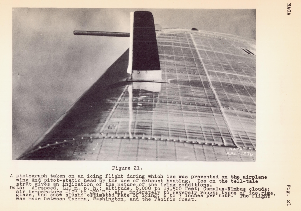
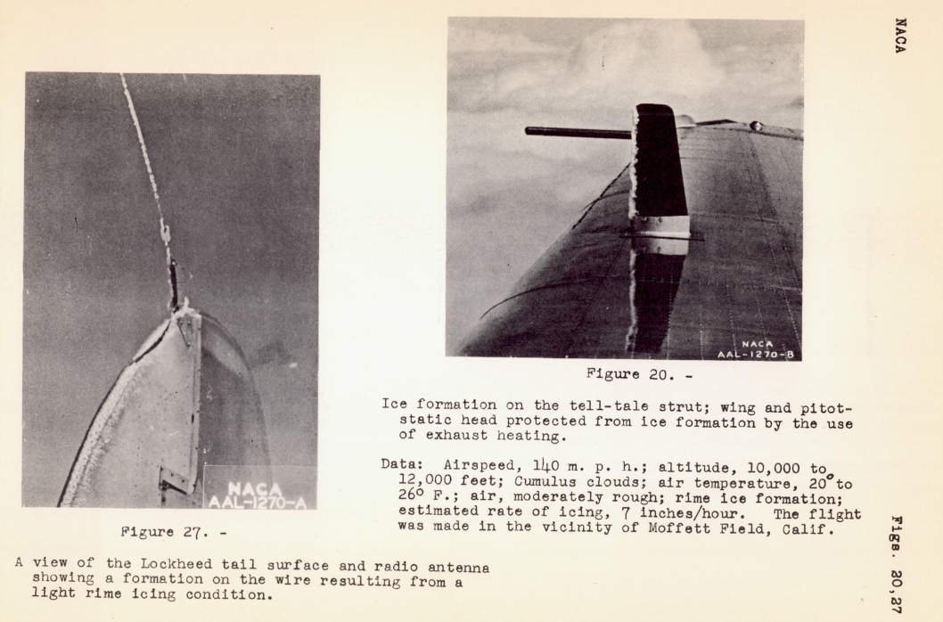
Flights have been made with and airplane in icing conditions in order to test the effect of exhaust gas heat applied to the wings as a means of preventing ice formations. Other ice-prevention equipment, including an exhaust gas-heated pitot-static head, hot-air-heated windshield, and an inflatable de-icer of recent design, were also tested...
The overall air flow went something like this (although with different venting):
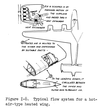
Figure I-8 from Modern Icing Technology. 5
The exhaust heated pitot tube and the wing exhaust vent are shown in Figure 18.
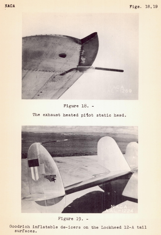
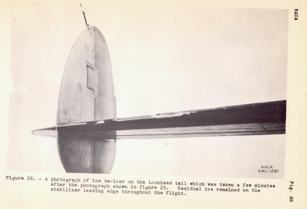
Ice was removed from the horizontal stabilizer by the inflatable de-icer under certain icing conditions, although other icing conditions the ice was only partially removed.
Important factors in the design of exhaust-heating equipment, in addition to the degree of ice protection afforded, such as corrosion, thermal expansion; failures resulting from vibration, and increased weight and cost have been considered. After about 50 hours of flying time, an inspection of the airplane indicated that while the need for maintenance and repairs had been found, a remedy for each defect was not difficult to discover.
CONCLUSIONS
1. Under all conditions of icing encountered in the flight tests, satisfactory protection against the formation of ice on the wing leading edges of the Lockheed 12A airplane was obtained by use of heat from the engine exhaust.
2. A consideration of the weight of exhaust wing-heating equipment, the effects of the equipment on the performance of the airplane, and the problem of maintenance of the exhaust-heated wings has immediate practical possibilities.
3. The use of air heating on the pilot's windshield and exhaust heating on the pitot-static head was found to provide satisfactory protection against ice on these parts.
The successful test experience with the Lockheed 12A would soon be repeated on two other aircraft (B-17 and B-24), using similar exhaust heating designs.
Conclusions
Exhaust heat provided a practical means of ice protection. It saw further use through the 1950s.
I do not know of any current aircraft that use engine exhaust heat for wing ice protection.
The coming jet age would require different means of ice protection, which we will review in the upcoming post on compressed air heat.
Citations
An online search (scholar.google.com) found
NACA-TR-403 is cited 14 times,
NACA-TN-712 5 times,
NACA-TN-783 0 times,
"Modern Icing Technology" 11 times,
NACA-ACR-A-53 0 times,
NACA-WR-A-34 5 times,
NACA-WR-A-39 4 times,
NACA-ARR-3H24 11 times,
NACA-WR-A-35 5 times,
and NACA-WR-A-7 5 times.
Curiously, none of these are listed in the 132 publications of the "Selected Bibliography of NACA-NASA Aircraft Icing Publications".
I view this as an under-appreciated area, as there is much to glean even if one is not building an exhaust heat system (particularly wing leading edge heat exchangers). There are many similarities to the now commonly used compressed air heating systems.
Also, detailed natural icing flight test accounts are always instructive (NACA-TR-403, NACA-TN-783, NACA-ACR-A-53, NACA-WR-A-7, NACA-ARR-4B02).
Notes
-
Theodorsen, Theodore, and Clay, William C.: Ice Prevention on Aircraft by means of Engine Exhaust Heat and Technical Study of Heat Transmission from a Clark Y Airfoil. NACA-TR-403, 1931. ntrs.nasa.gov ↩↩
-
Rodert, Lewis A.: A Preliminary Study of the Prevention of Ice on Aircraft by use of Engine Exhaust Heat. NACA-TN-712, 1939. ntrs.nasa.gov ↩
-
Rodert, Lewis A., and Jones, Alun R.: A Flight Investigation of Exhaust Heating De-icing. NACA-TN-783, 1940. ntrs.nasa.gov ↩
-
Rodert, Lewis A., and Jackson, Richard: Preliminary Report on Flight Tests of an Airplane having Exhaust-Heated Wings. NACA-ACR-A-53, April 1941. ntrs.nasa.gov ↩
-
Tribus, Myron: "Modern Icing Technology" 1952. lib.umich.edu ↩
-
Rodert, Lewis A., and Jackson, Richard: Preliminary Investigation and Design of an Air-Heated Wing for Lockheed 12A Airplane. NACA-WR-A-34, April 1942. ntrs.nasa.gov ↩
-
Rodert, Lewis A. and Jackson, Richard: A Description of the Ju 88 Airplane Anti-Icing Equipment. NACA-WR-A-39 1942. ntrs.nasa.gov ↩
-
Jones, Alun R., and Rodert, Lewis A.: Development of Thermal Ice-Prevention Equipment for the B-17F Airplane. NACA-ARR-3H24, 1943. ntrs.nasa.gov ↩
-
Jones, Alun R., and Rodert, Lewis A.: Development of Thermal Ice-Prevention Equipment for the B-24D Airplane. NACA-WR-A-35, Feb. 1943. ntrs.nasa.gov ↩
-
Neel, Carr B., Jr., and Jones, Alun R.: Flight Tests of Thermal Ice-Prevention Equipment in the XB-24F Airplane. NACA-WR-A-7, Oct. 1943. ntrs.nasa.gov ↩
-
Look, Bonne C.: Flight Tests of the Thermal Ice-Prevention Equipment on the B-17F Airplane. NACA-ARR-4B02, 1944. ntrs.nasa.gov ↩