"In spite of the simplicity, the configurations are reasonable approximation of those found on aircraft"
NACA-TR-1317.
From NACA-TR-1317.
NACA-TR-1317, "Cloud-Droplet Ingestion in Engine Inlets with Inlet Velocity Ratios of 1.0 and 0.7."
and
NACA-TN-4268, "Droplet Impingement and Ingestion by Supersonic Nose Inlet in Subsonic Tunnel Conditions."
Summary
"Important general concepts" of impingement on engine inlets are illustrated.
Introduction
In the first title here, the use of potential flow to determine water-drop trajectories gets pushed to the limit. In a demonstration of the pragmatism that ran through much of the ice protection development at NACA, investigators produced results on configurations that could be analyzed that were close enough to real aircraft geometries.
In NACA-TN-3770, we enter the supersonic jet age, with a dye-tracer method test of a supersonic inlet (but at a lower Mach number). We will see a test of "the configurations are reasonable approximation".
Discussion
Inlet impingement analysis, NACA-TR-1317
Readers will find many similarities to the ellipsoid analyses in Bodies of Revolution and Shadow Zones and Concentration Zones.
There are insights "to important general concepts" here, and many approximations to overcome the limitations of the "facile" potential flow methods used.
SUMMARY
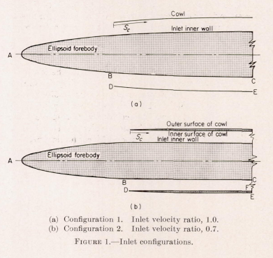
The path of cloud droplets into two engine inlets have been calculated for a wide range of meteorological and flight conditions. The amount of water in droplet form ingested by the inlets and the amount and distribution of water impinging on the inlet walls are obtained from the droplet-trajectory calculation . In both types of inlet, a prolate ellipsoid of revolution represents either part or all of the forebody at the center of an annuLar inlet to an engine. The configurations can also represent a fuselage of an airplane with side-scoop inlets. The studies were made at an angle of attack of 0°. The principal difference between the two inlets studied is that the inlet-air velocity of one is 0.7 that of the other. The studies of the two velocity ratio lead to some important general concept of water ingestion in inlets.INTRODUCTION
A part of a comprehensive program on cloud-droplet-trajectory computation, the NACA Lewis laboratory has calculated the paths of droplet ahead of and surrounding prolate ellipsoids of revolution moving through clouds (ref. 1 to 4). The present report extends the trajectory computation with respect to prolate ellipsoids in an incompressible flow field to include the study of water ingestion into two engine inlets a 0° angle of attack. In both inlets, an ellipsoid represents either part or all of the forebody at the center of an annular inlet to an engine, or some other air-processing device. In either inlet, the ellipsoid can also be assumed to approximate the fuselage of an airplane so that the inlets become side ram-scoop inlets. The configurations, which are described in detail in the following section, are geometrically simple in order to permit the studies described herein. In spite of the simplicity, the configurations are reasonable approximation of those found on aircraft. The results of the studies on the two simple shapes lead to important general concepts of water ingestion in to inlets of this type.The ellipsoids chosen for this study are 10 and 20 percent thick (fineness ratio of 10 and 5, respectively) for configuration 1 (fig. l (a)) and 10 percent thick for configuration 2 (fig. 1 (b)) . The problem is limited to an angle of attack of 0° between the major axis of the ellipsoid and the free-stream air, because the facile methods of calculating the flow field and trajectories are limited to 0°.
CONCLUDING REMARKS
The data presented herein can be used as a guide in the evaluation of water ingestion in inlets. The studies on the simple shapes at 0 angle of attack lead to some general concepts of water ingestion in inlets. The amount of water ingested is not sensitive to small changes in shape of the outer wall. The placement of a wall in the airflow will usually disturb the airflow more than the droplet trajectories. The impingement on the cowl (i.e. , amount and distribution) is quite sensitive to the physical shape and surface condition of the wall. In most applications impingement on the interior surface of the cowl can be expected for a considerable distance inside the entrance, because the forebody deviates the trajectories away from the body and toward the cowl.
The use of screens and boundary-layer-removal scoops at the entrance requires careful design because of the existence of the shadow zone and regions of high concentration. The variation in concentration of water across an inlet shows that a screen can build up ice unevenly in such manner as to result in large radial-flow distortions.
Although only one inlet configuration was studied at an inlet velocity ratio of 0.7, the general concept that lowering the inlet velocity ratio lowers the ingestion efficiency can be applied to a large variety of configurations. This concept is evident from a study of the manner in which air streamlines change when the inlet-air velocity ratio is decreased for a particular configuration. Since most aircraft (particularly interceptor types) should be designed with protection against ice formations during loitering, climb, and letdown, a design based on water-ingestion data for an inlet velocity ratio of 1.0 will be adequate for lower velocity ratios. A lowering of the velocity ratio will also result in higher impingement near the inlet opening on the inner surface of the cowl.
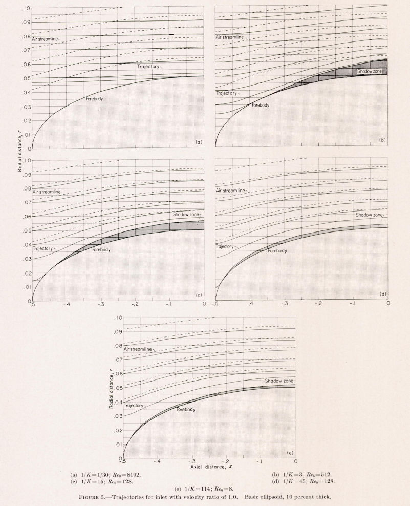
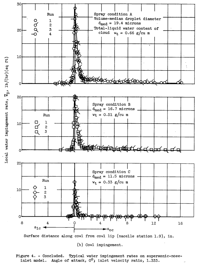
As can be seen from figures 5 and 19, no impingement occurs on the outer surface of the cowl over a large range of meteorological and flight conditions. High local impingement efficiencies can be expected on the cowl lip for all entrance velocity ratios.
During the major portion of most flight plans the inlet velocity ratio does not exceed 1.0 and does not decrease below 0.7. For most inlet designs, the accuracy of the methods presented herein for estimating amount and distribution of impingement is within the accuracy of knowledge of the meteorological factors involved, such as liquid-water content and droplet size.
As was stated early in this report, droplets that impinge on the forebody are assumed to be removed from the possibility of entering the inlets. In reality, the water deposited on the forebody may run back over the body surface and into the inlet when the ice is melted by thermal anti-icing devices. A discussion of runback is beyond the scope of this report. The conditions resulting in runback and the effect of runback on screens, boundary-layer scoops, and other devices in the inlets should be carefully considered in inlet designs.
Although the calculations were made for incompressible flow, they should be applicable throughout the subsonic region because of the small effect of compressibility on droplet trajectories (ref. 5) and the high flight critical Mach number of the configurations studied.
Impingment tests, NACA-TN-4268
SUMMARY
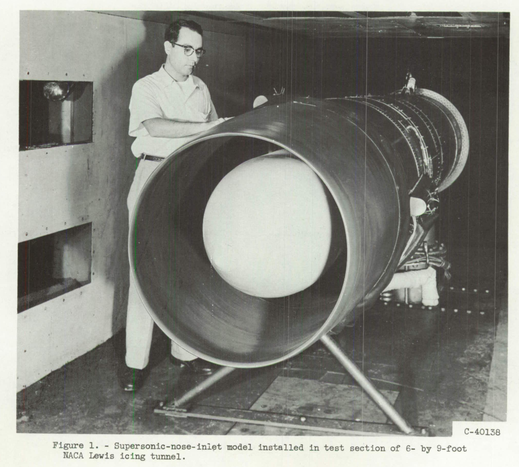
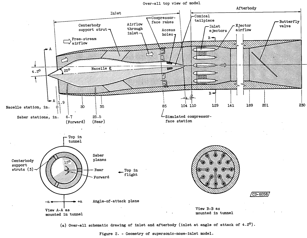
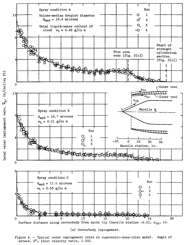
The amount of water in cloud droplet form ingested by a full-scale supersonic nose inlet with conical centerbody was measured in the NACA Lewis icing tunnel. Local and total water impingement rates on the cowl and centerbody surfaces were also obtained. All measurements were made with a dye-tracer technique. The range of operating and meteorological conditions studied was: angles of attack of 0 and 4.2, volume-median droplet diameters from about 11 to 20 microns, and ratios of inlet to free-stream velocity from about 0.4 to 1.8. Although the inlet was designed for supersonic (Mach 2.0) operation of the aircraft, the tunnel measurements were confined to a free-stream velocity of 156 knots (Mach 0.237). The data are extendable to other subsonic speeds and droplet sizes by dimensionless impingement parameters.
Impingement and ingestion efficiencies are functions of the ratio of inlet to free-stream velocity as well as droplet size. For the model and range of conditions studied, progressively increasing the inlet velocity ratio from less than to greater than 1.0 increased the centerbody impingement efficiency and shifted the cowl impingement region from the inner- to outer-cowl surfaces, respectively. The ratio of water ingested by the inlet plane to that contained in a free-stream tube of cross-section equal to that at the inlet plane also increased with increasing inlet velocity ratio. Theoretically calculated values of inlet water (or droplet) ingestion are in good agreement with experiment for annular inlet configurations.These data were obtained in the NACA Lewis icing tunnel by using the dye-tracer technique.
There was a comparison of results to those in NACA-TR-1317. One might call them, at best, approximately similar configurations.

However, at least for the comparison of concentration factor (Ct) values, the results are similar. (The theoretical values may be difficult to discern in amongst the test results.)
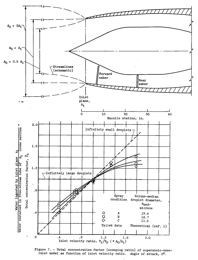
Although the value of Ct for fully annular inlets of this type appears relatively insensitive to changes in the inlet configuration as indicated by figures 7 and 8, local impingement rates or limits of impingement on the inlet surfaces, or both, probably will be significantly different for small changes in the inlet configuration.
Generalization of Impingement and Ingestion Characteristics
In the literature, local and total collection efficiencies and impingement limit are usually presented as functions of K and φ. The parameter K indicates the inertia of the droplet, and φ represents the deviation of the droplet drag forces from Stokes' law. As discussed and illustrated in references 26 and 22, Smax, β, and Em can be correlated with reasonable accuracy with one independent parameter - the modified inertia parameter; likewise, the amount of water ingested should be amenable to this treatment. The modified inertia parameter Ko (Ko = λ/λs K; λ/λs = f(Reo), see ref. 22) accounts for the pertinent impingement variables of droplet size, body size, airspeed, and altitude. Use of the Ko parameter yields a set of points for any dependent impingement factor (Smax, β, or Em) that can be essentially represented by a single curve, independent of φ; this curve is approximately the solution using Stokes' law for sphere (droplet) drag. From experience with the Ko parameter, limited experimental or theoretical impingement and ingestion data can be reasonably extended or interpolated over a wide range of variables although no complete substantiation of its significance or validity is currently available.
With a cloud composed of nonuniform droplet sizes, impingement and ingestion efficiencies are correlated with Ko,med (Ko calculated with d_med). Because the limit of impingement is a function of the maximum droplet diameter present in the cloud, Smax will be correlated with Ko,max (Ko calculated with d_max).
Conclusions
Concluding Remarks
Reference 24 implies that the unknown impingement of a body may be approximately equal to the known impingement of a reference body provided the local surface pressure (or velocity) distributions of the reference body can be made approximately equal to those of the unknown body by varying angle of attack or chord length or both. In particular, the pressure distributions and surface contours need be similar in the impingement regions of both bodies. Extending this reasoning to an annular inlet such as the type studied herein suggests the possibility of estimating cowl and centerbody impingement from the known impingement of several airfoils (refs. 11 to 18 and 22) and bodies of revolution (refs. 7, 8, 23, and 27). Demonstration or proof of the validity of such an analysis is beyond the scope of this report.
Most of the reported data on droplet size and liquid-water content of natural icing clouds has been obtained with the rotating multicylinder method (ref. 2). Such values are readily converted to the slightly different ones quoted herein for the tunnel cloud (by Joukowski-aspirator method) by figure 19 of reference 22. A sample calculation applying tunnel impingement data to flight conditions is given in reference 22.
Reference 24 is NACA-RM-E56E11, "Use of Truncated Flapped Airfoils for Impingement and Icing Tests of Full-Scale Leading-Edge Sections", which was briefly reviewed in Scaling in NACA tests.
Reference 22 is NACA-TN-3839, which we will see in the upcoming review "Impingement on Airfoils".
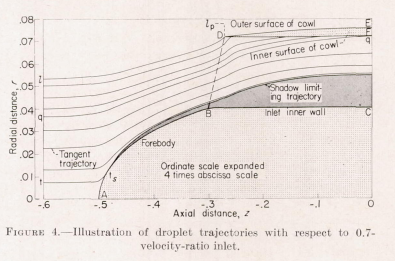
At a company I worked at we had an internal design manual that cataloged dozens of impingement analysis for several inlets. The results were similar to Figure 4 above, all with the same general trends, but there were differences in the details.
Citations
From scholar.google.com:
NACA-TR-1317: 8 citations
NACA-TN-4268: 12 citations
Related
This is part of the Water Drop Impingement on Surfaces thread.
Notes
-
Brun, Rinaldo J.: Cloud-Droplet Ingestion in Engine Inlets with Inlet Velocity Ratios of 1_0 and 0_7. NACA-TR-1317 (supersedes NACA-TN-3593), 1956. ntrs.nasa.gov ↩
-
Gelder, Thomas F.: Droplet Impingement and Ingestion by Supersonic Nose Inlet in Subsonic Tunnel Conditions. NACA-TN-4268, 1958. ntrs.nasa.gov ↩