"The industry has now passed through the experimental stages of heating and anti-icing ..." (1946) 1
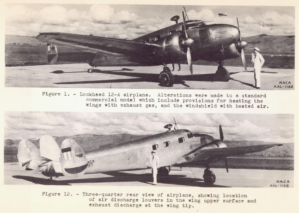 From NACA-ACR-A-53, 1941.
Summary
Ice protection system development continues to address new challenges.
Key Points
- Design guides can lead you to "adequate" designs for several technologies.
- Design guides provide procedures to compare candidate systems.
- Optimal designs and new requirements may require system development.
Discussion
We have seen "the possible methods for overcoming the ice hazard" that were developed in the NACA-era in this Ice Protection Thread. The period up to and through WWII (1945) was largely characterized by expeditious tests to address immediate icing problems.
The quote above "The industry has now passed through the experimental stages of heating and anti-icing ..." from 1946 was not completely the case, but NACA did move on to more planned scientific and engineering tests and analysis methods development. By the 1950's useful Engineering Design Manuals were available, so that every new application did not have to be a major research and development effort. The ADS-4 Design Manual published in 1963 was a crowning achievement of the NACA-era (ADS-4 was published after the NACA era, but it was included in Uwe von Glahn's "Selected Bibliography of NACA-NASA Icing Publications").
NACA-TR-403 said in 1931:
"an airplane that will be immune from the dangers of ice accumulation ... is only a matter of technical development."
The prediction above and the "destiny" noted below of all-weather aircraft had thus been achieved:
“The greatest advance that can be made in air transport from its present level,” said Edward P. Warner in 1946, “is not in speed, or even in economy, important as that is, but in regularity. When cancellations on account of weather are eliminated, or even reduced to a fifth or a tenth of their present number, air transport’s whole status will be changed.” It is difficult to see how aviation can come into its full destiny as an every-day competitor of steamships and railroads unless airplanes are made capable of flying in any weather.
Excerpts from George W. Gray, Chapter 14, “Heat Against Ice,” in Frontiers of Flight: The Story of NACA Research, reprinted in "The Wind and Beyond: Journey into the History of Aerodynamics in America, Volume 2, Reinventing the Airplane.", NASA-SP-4409, 2007. http://history.nasa.gov/sp4409-vol2.pdf
However, ice protection system development continues. While the design methods in ADS-4 may yield an "adequate" ice protection system, it may not be optimal. Systems have been developed since the NACA-era, such as electro-impulse de-icing or EIDI, and ice phobics have long been studied (90+ years, see NACA-TN-313 and NACA-TN-339), and may yet see improvements.
Also, ice protection is being applied to aircraft other than the transports largely considered in the NACA-era. Unmanned aircraft can be almost any size, including rather small. Some mission profiles may have extended durations in potential icing conditions. Some applications may be able to tolerate schedule interruptions due to weather, while others may need all-weather capability. All-electric aircraft have unique advantages and challenges. I did a cursory search and easily found 18 companies currently working on all-electric aircraft, and I do not doubt that there are many more.
Analysis methods developed after the NACA-era, such as 3D computational fluid dynamics (CFD), allow optimizations of designs. This is an area of ongoing research and development.
System Selection
We have seen many possible methods for ice protection. How do airplane designers choose from among them?
The Aircraft Icing Handbook 3 has sections describing ice protection methods (including one that we did not see in the NACA-era, electro-impulse de-icing or EIDI). It also has a section on selecting from among the options. The Aircraft Icing Handbook in general drew heavily from the prior ADS-4. ADS-4 has similar sections on system selection, but this section of the Aircraft Icing Handbook is largely newer (circa 1991) material.
While not detailed, some NACA-era technologies, engine exhaust heat and combustion heated air, make cameo appearances.
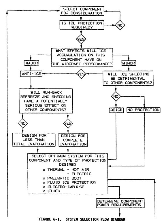
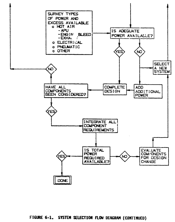
III.6.1 SELECTION CRITERIA
The available ice protection methods for various aircraft surfaces and components have been discussed in previous sections of this chapter. It should be noted that there is no one best system for use on all types of aircraft and each aircraft represents an independent design problem for ice protection. The following considerations should be made in the selection of the best ice protection system for a particular aircraft:
a. What is needed for flight in known icing conditions? For aircraft operating in the temperate zone, service experience indicates that holding in icing conditions for as long as 45 minutes is an expected operating condition. Icing probabilities and characteristics are discussed in Section 1.1.0 and certification requirements are discussed in Chapters V and VI. Generally, ice protection systems should be capable of ice removal or prevention at altitudes from sea level to 22,000 feet (6700 m) with temperatures of 32 F (0 C) to -22 F (-30 C) and with LWC of 0 to 2.8 g/m3.
b. What is the effect of icing on the aircraft's performance? Analysis and flight tests of the aircraft and components should be performed to determine ice impingement limits, worst case ice shapes, and the effect of this on aircraft performance and handling characteristics. For example, some aircraft are sensitive to empennage icing and others can tolerate unprotected empennage surfaces. Section 1.2.3 discusses aerodynamic penalties of ice.
c. What power is available for ice protection systems? Compressor bleed air may be available from gas turbine engines. Hot air from exhaust gas heat exchangers may be used in piston engines. Hot exhaust gas alone is rarely used due to its corrosive nature. A separate combustion heater transferring its heat to air is another alternative. High temperature air could be provided by an Auxiliary Power Unit (APU) compressor. Surplus electrical power may be available or could be provided by a larger capacity generator or an auxiliary generator. Some light aircraft have used electro-thermal and fluid ice protection systems with good results.
d. In view of the power available and the components needing ice protection, which of the ice protection methods discussed in this chapter are candidates for the particular aircraft in question? Examination of the trade-offs between the benefits and costs of the candidate systems suitable for each aircraft component must be performed. Costs include system weight, power consumption, maintenance, and required system testing, in addition to initial and development costs.
e. Will two or more types of ice protection system be needed? Often propellers and windscreens are de-iced or anti-iced by electric resistance heaters while aerodynamic surfaces are pneumatic boot or hot gas de-iced. Many other combinations occur. This may increase inspection and maintenance complexity.
f. Other considerations which sometimes apply include:
- Run-back icing concerns
- Aerodynamic smoothness requirements
- Maintenance requirements
- Installation costs and time, if the system is being retrofitted
- Confidence in the selected system based on previous experience in similar applications
- Electromagnetic interference concerns
- Environmental impact concerns
- Certification difficulties anticipated
- Redundancy requirements
The "other considerations" are often difficult to quantify, but they can be critical to your system selection.
Figure 6-1 is a flow diagram that can be used in the system selection process. Following this procedure should result in the optimum system for each component to be protected with the only constraint being adequate power available. After the totally integrated system is complete, factors such as cost, weight, reliability, and environmental impact should be considered or reconsidered. It is quite possible that any one of these may force a redesign of some of the component systems.
...
III.6.4 WEIGHT, ENERGY, AND POWER COMPARISONS
Weight, energy and power requirement comparisons for ice protection system on four typical aircraft (figure 6-2 through 6-5) are presented in tables 6-1 through 6-8.
For brevity, we will look at the large transport aircraft only (there are also figures for small single engine aircraft, small twin engine aircraft, business jet, and rotorcraft).
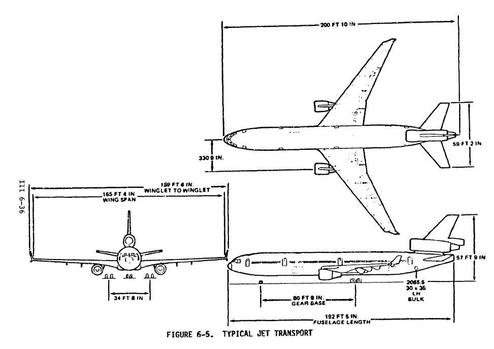
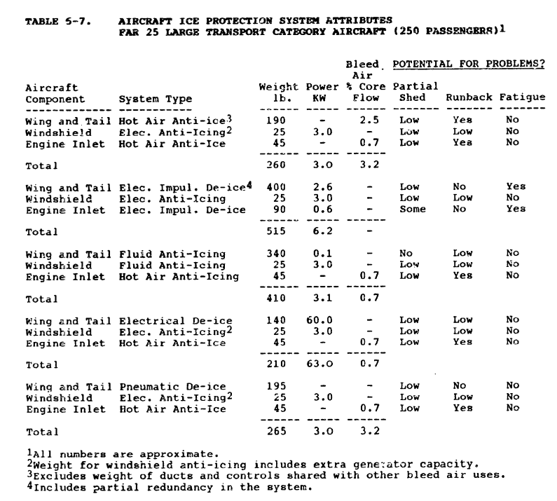
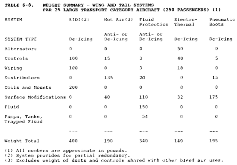
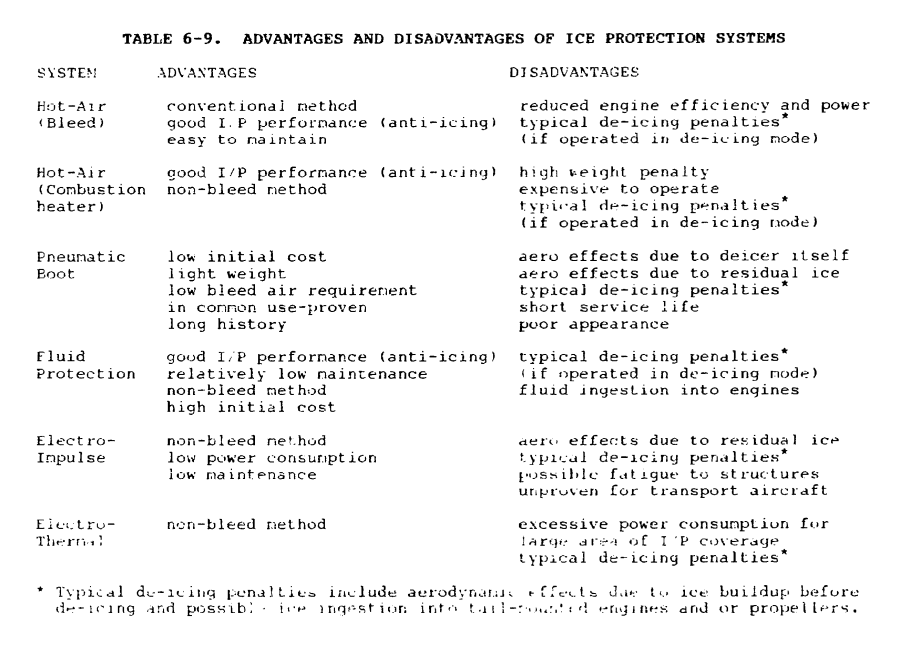
Looking at Table 6-8, the electrothermal de-icing system is the lightest. However, in Table 6-9, note the asterisk (*) for electrotheral (deicing).
Typical de-icing penalties include aerodynamic effects due to ice buildup before de-icing and possible ice ingestion in tail-mounted engines and propellers.
These considerations may weigh against the selection of a deicing system.
...
III.6.6 DISTINCTIVE TRANSPORT CATEGORY AIRPLANE PROBLEMS (FAR PART 25) Aircraft in this category can be either small, medium or large and each would have somewhat distinctive ice protection problems. Added to this is the complication that these aircraft can be powered by piston engines, turboprop engines and propellers, or jet engines (high or low bypass ratio). A distinctive advantage of these aircraft lies in the availability of bleed air and relatively large amounts of power for ice protection. Thus all forms of ice protection can be supported. The use of more than one type is likely because this flexibility allows the designers to install the optimum system for each component that is to be protected.
An ice protection area that is perhaps unique to this category of aircraft is wing leading edge devices. The possible need for radome ice protection is a consideration for aircraft in this category which need not be addressed for some Part 23 aircraft.
I agree with the statement "there is no one best system for use on all types of aircraft". You will have to determine for your aircraft and mission profile what system fits it best.
Recent certification requirements for supercooled large drop (SLD) icing, which are not addressed in the Aircraft Icing Handbook, may also influence system selection.
The 787 wing ice protection system
I was the principal investigator of the 7E7 (a study airplane configuration) technology development for wing ice protection. The 7E7 study selected electrothermal ice protection. The 7E7 soon became the Boeing 787, a twin-engine jet with largely composite structure. The wing ice protection on the 787 is electrothermal heat, in either an anti-icing or deicing mode.
While the NACA lessons learned noted previously in this thread are valuable for electrothermal design, there are details to be worked out to applying the general technology to a specific application.
There are numerous instructive details about the design, many of which are proprietary to three entities (Boeing, GKN, and Ultra Electronics). It is difficult to publish much about the system without all three involved, and I have seen few details published.
An article describes some of the rationale for the "no bleed" architecture.
NO BLEED, MORE ELECTRIC SYSTEMS ARCHITECTURE
It would be very challenging to provide enough power for electrothermal wing anti-ice, unless the power supply system is specifically designed considering all the airplane power requirements, including wing anti-ice.
A video produced by Ultra Electronics gives an overview of the wing ice protection system.
787 Wing Ice Protection System Video
An article describes some of the details of the electronic controls.
MDE Semiconductor, Inc. TVS Diode Clamp Devices Provide Protection to Boeing 787 Dreamliner’s Unique Electro-thermal Wing De-icing System
The 787 electrothermal system?
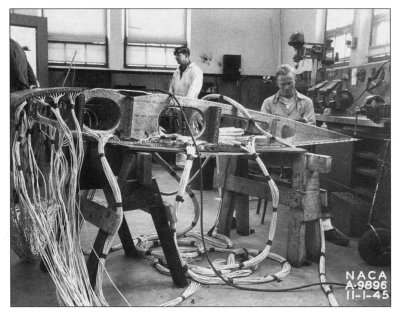
No, but it does have a lot of wires.
(C-46 Lab Flight Test Article.)
And lest someone think that I had a bias toward electrothermal technology, I was the equipment manager for the 777 wing and engine inlet ice protection systems, which are hot air based. I also conducted many system trade studies, including alternative airplane configurations such as the Sonic Criuser.
Conclusions
While the NACA-era knowledge that is encapsulated in design guides is useful for determining "adequate" ice protection, optimal systems for new aircraft configurations and new technologies may still require research and development.
Related
The next thread in the NACA review series is the Icing Cloud Meteorology Thread.
Notes
-
Draney, John J.: "Heat Recovery Applied to Heating and Anti-Icing of Aircraft". SAE Transactions, Vol. 54, 1946. ↩
-
Theodorsen, Theodore, and Clay, William C.: Ice Prevention on Aircraft by means of Engine Exhaust Heat and Technical Study of Heat Transmission from a Clark Y Airfoil. NACA-TR-403, 1931. ntrs.nasa.gov ↩
-
“Aircraft Icing Handbook Volume 1.” DOT/FAA/CT-88/8-1 (1991) apps.dtic.mil.
Also note that there was a perhaps little known update in 1993 (that did not affect the pages of interest herein): apps.dtic.mil. ↩