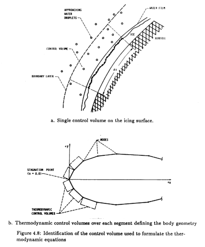
from Users Manual for the NASA Lewis Ice Accretion Prediction Code (LEWICE) (1990 version) ntrs.nasa.gov
Prerequisites
You need to complete the Aircraft Icing Handbook Water Catch Examples.
You need to select a computerized tool to work with. See Analysis Toolset for obtaining LEWICE, and some other options.
If you have chosen to use LEWICE, but you have not run it before, see the LEWICE Quick Start.
Introduction
We will compare energy balance terms and freezing rates calculated with the Standard Computational Model and LEWICE (or the tool that you have selected).
The values found by differing methods are generally similar, but rarely identical.
Aircraft Icing Handbook Example 2-4
The mass of ice accretion on the NACA 0012 section will be calculated. Using the same flight conditions as Example 2-1. and the droplet size distribution and value from Example 2-3:
Airfoil                         c = 3.1 foot chord NACA 0012
Flight Speed:                   V = 200 kt
Airfoil projected height:       h = 0.12 at alpha = 0
Liquid Water Content:           LWC = 0.4 g/m^3
Ambient Temperature:            T = -4 F
Collection efficiency:          E = 0.24
Maximum impingement efficiency: Beta_max = 0.65
Icing time:                     tau = 5 minutes
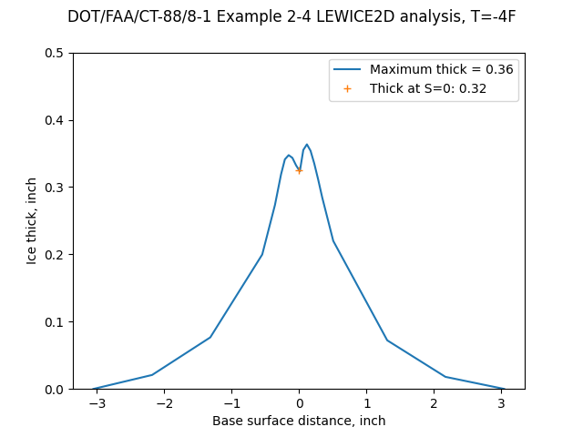
The LEWICE analysis at the nominal -4F does not predict complete freezing at the leading edge:
Public domain image by Donald Cook.
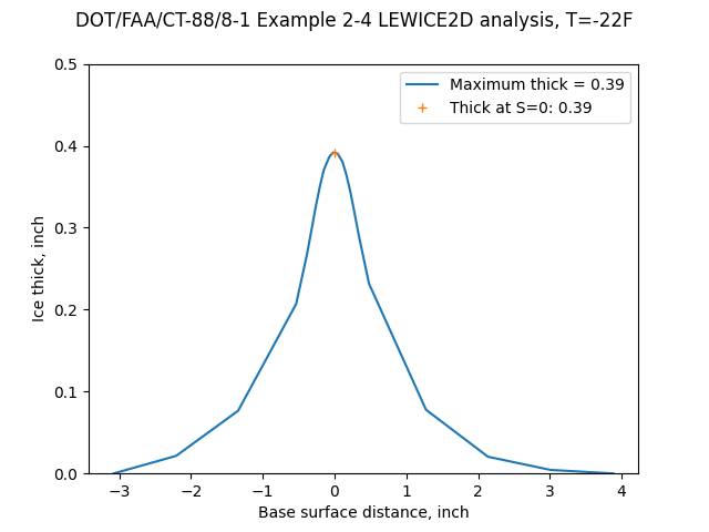
Here is the result at a colder temperature (-22F):
Public domain image by Donald Cook.
Here are the computed ice shapes:
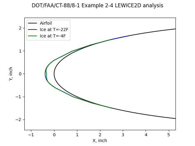
Public domain image by Donald Cook.
The ice calculated at -22F agrees well with the ice thickness from the handbook example.
Method                          Leading edge ice thick, inch
Handbook                        0.39
Standard Computational Model    0.393
LEWICE -4F                      0.32
LEWICE -22F                     0.39
20 cm diameter cylinder example
The icing time was not specified, so we will assume the same value as example 2-4.
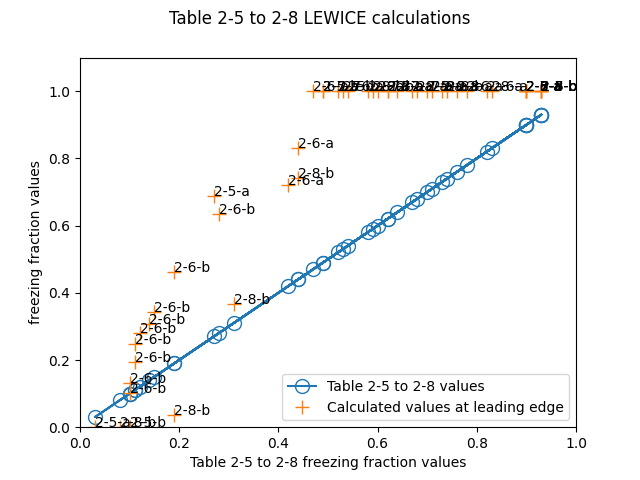
Public domain image by Donald Cook.
The results do not appear to agree well. Many of the LEWICE results are that the freezing fraction is 1, while the Table 2-5 to 2-8 values show a range of results.
Freezing rates
While the freezing fraction is a non-dimensional term, freezing rate is a dimensional term (kg/m^2-s).
The freezing rate can be used to calculate ice thickness, and with a multiple control volume analysis, ice shapes.
Results from LEWICE and the Standard Computational Model are compared below. General trends agree, but the values may have large differences.
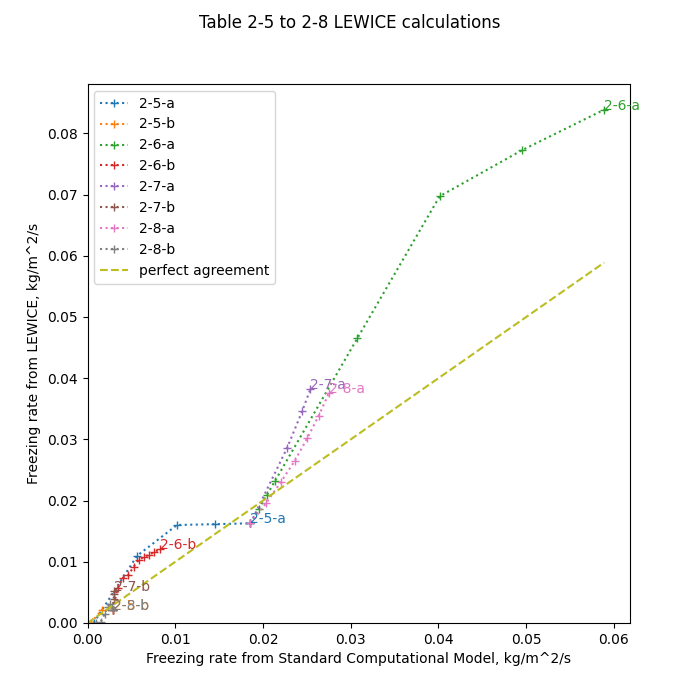
Public domain image by Donald Cook.
A partial explanation of differences in reported freezing fraction
The integral boundary layer method implementation used in LEWICE has results that agree reasonably well with the stagnation line results from the Standard Computational Model. So, differing heat transfer coefficient values are only a small component in the differences. Here is the Table 2-5-a case at -8C temperature:
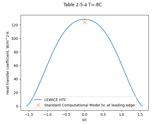
Public domain image by Donald Cook.
However, the stagnation line (S=0) Beta value differs from that calculated using the Standard Computational Model:
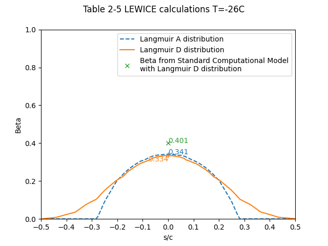
Public domain image by Donald Cook.
The LEWICE manual ntrs.nasa.gov states:
The icing model, which was first developed by Messinger, is used to calculate the ice growth rate at each point on the surface of the geometry.
However, it actually uses a modified Messinger method. The LEWICE implementation adds a heat term to the Messinger heat balance for conduction to the surface where ice is forming (the unnamed, first term in the equation below):
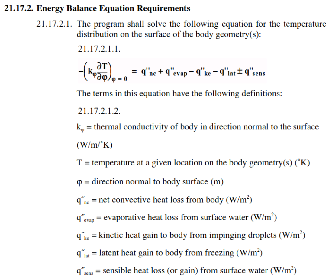
While the manual is not explicit, this is a transient heat term that changes with time (you have to review the code to get the details). The time step used affects the analysis, even for the first ice layer, which starts with at clean surface.
Conclusions
While the examples here are for LEWICE, you are likely to also find differences between analytic values for the heat balance terms and the results from any other computer icing simulation. The implementation details, which are sometimes not well documented, can lead to non-trivial differences.
Resources
User's Manual for LEWICE Version 3.2 ntrs.nasa.gov
Note that a "manual.pdf" file comes with the LEWICE software distribution (apparently for version 3.0),
and a file "Lew32manual_changes.doc".
I find it easier to just use the Version 3.2 manual.
Related
Back to Intermediate Topics