The size of water drops in clouds
The water that causes most aircraft in-flight icing is small drops in clouds. Average drop sizes are typically 10 to 50 "Micrometers" (μm) in diameter (for comparison, a human hair is about 50 to 100 micrometers in diameter).
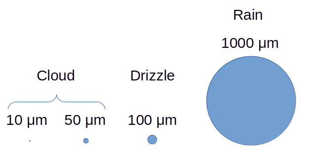
Typical drop sizes, approximately proportional. Public domain image by Donald Cook.
In a particular cloud, not all water drops are the same size. The "Langmuir Drop Size Distributions" describe an idealized approximation of how the drop sizes vary in a cloud about an average or median drop size. It has seven bins, each with a representative drop size and fraction of the total water content in the cloud.
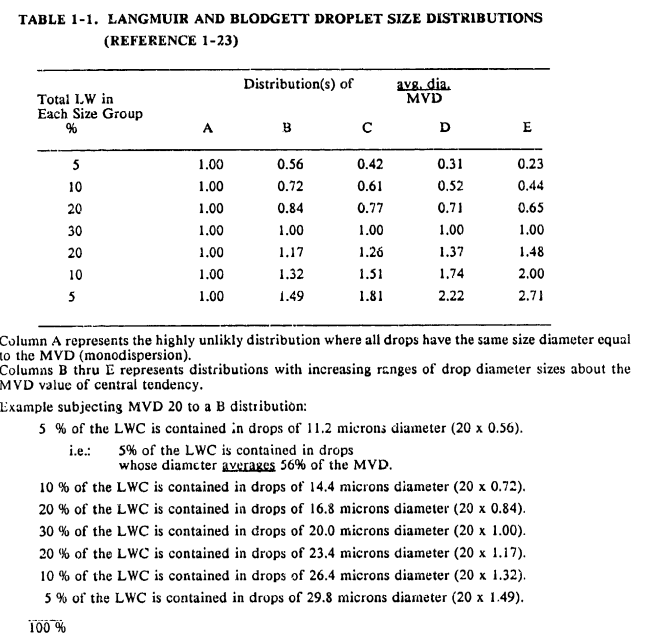
from "Aircraft Icing Handbook Volume 1", DOT/FAA/CT-88/8-1 apps.dtic.mil
The impingement of water drops on aircraft surfaces
Calculating the amount of water that hits or impinges on the surface of an airplane as it flies through a cloud is an important step that is required to calculate ice shapes, and to determine the amount of ice protection required.
Air flow around an airfoil in flight can be idealized as streamlines, which may be parallel far from an object, but bend around an object close to it. Mathematical models are available to calculate streamlines. Streamlines can be visualized in a wind tunnel using smoke traces (a source that makes a thin line of smoke that shows how the airflow bends).
Water drops tend to follow streamlines far from an object, but due to their momentum, diverge from streamlines near an object. Calculations of the paths of water drops, termed water "Drop Trajectories", are in some ways more complicated than the air flow calculations. There is no simple way to directly visualize water drop trajectories in experiments.
Streamlines and water drop trajectories around a cylinder
(airflow is from left to right, or, alternatively, the cylinder is moving from right to left through stationary air and water drops):
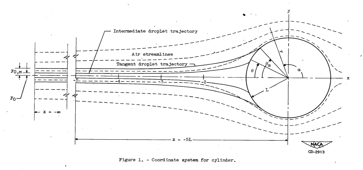
from "Impingement of Cloud Droplets on Aerodynamic Bodies as Affected by Compressibility of Air Flow Around the Body". NACA-TN-2903, 1953 ntrs.nasa.gov
As water drop trajectories diverge around an object, not all drops in the frontal view of the object impinge on the object. The fraction of water drops that do impinge is termed the water "Collection Efficiency". Once drops impinge on a surface they tend to remain on the surface. The water collection efficiency can vary widely, depending on factors such as the water drop size and object size, airspeed, air pressure, and others. The water collection efficiency can also be zero for some cases (such as very small water drops, a very large object, and a low airspeed).
The trajectories of water-drops that impinge are used to calculate the collection efficiency, which is the ratio of the area of impingement to the frontal area (Em in the figure below).
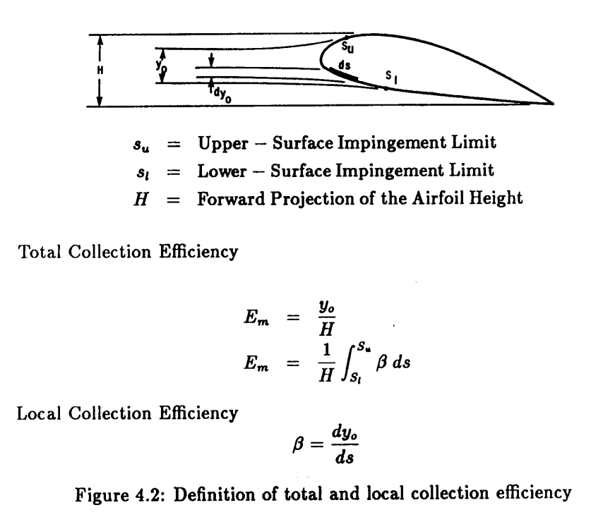
from Users Manual for the NASA Lewis Ice Accretion Prediction Code (LEWICE) (1990 version) ntrs.nasa.gov
The water drops do not impinge everywhere on a surface, they tend to only hit near the leading edge. The limits of where they hit is termed "Impingement Limits". These can vary with conditions details such as airspeed and drop size.
Characterizing the icing atmospheric conditions
Much study has been done on the conditions that cause icing on an aircraft in flight. The data were collected into graphs in design documents and certification requirements. They give expected values for intensity or concentration of supercooled water in g/m^3 ("Liquid Water Content" or "LWC"), and mean or average drop size ("Mean Effective Drop Diameter" "MED" or "Median Volumetric Diameter" "MVD"). Other factors also have to be specified, such as temperature and altitude, for a complete definition.
Part of the definition of "Appendix C" icing conditions:
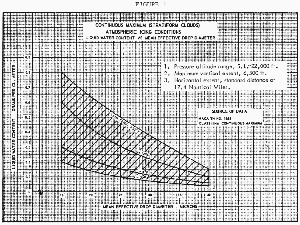
from Part 25 Appendix C (1964) ecfr.gov
"Continuous Maximum Icing Conditions" are for "Stratus" or layer-type clouds, which can extend for several miles.
"Intermittent Maximum Icing Conditions" are for "Cumulus" or "storm" type clouds, which extend over a lesser distance, but have more intense icing conditions.
Regulations cover large drop icing conditions, termed "Appendix O", were published in 2014. These have lWC values and extents roughly comparable to Continuous Maximum Icing Conditions, but have larger drop sizes. There are four detailed conditions definitions. The "Freezing Drizzle" definition includes drop sizes over 200 micrometers. The "Freezing Rain" definition includes drop sizes over 1000 micrometers. The larger drops can cause icing in locations where Appendix C size drops do not reach.
Resources
Appendix C ecfr.gov
Appendix O ecfr.gov
"Aircraft Icing Handbook", DOT/FAA/CT-88/8 apps.dtic.mil,
Chapter 1, Sections 1 and 2.2.1 in particular.
Also note that there was a perhaps little known update in 1993: apps.dtic.mil The update contains only the updated pages.
This worked fine when one printed the pages, punched holes, and manually substituted them into a three ring binder,
but not so well in the digital age.
I do not know of a pdf file that integrates the two into one.
“Engineering Summary of Airframe Icing Technical Data”, FAA Technical Report ADS-4, 1963 apps.dtic.mil
Chapter 2 in particular. This has more figures of impingement correlation than DOT/FAA/CT-88/8.
Related
This is part of The Basics series.