"It has been shown that the temperature of the surface of the wing in conditions of icing can be predicted with considerable exactitude from the temperatures measured in clear air."
"An Analysis of the Dissipation of Heat in Conditions of Icing from a Section of the Wing of the C-46 Airplane" 1
Summary
Two-dimensional heat balance equations for ice protection are detailed.
Key points
- Heat balance equations for ice protection are detailed.
- An assumption about water drop temperature approaching an object is made.
- A cylinder approximation for an airfoil leading edge is used for water drop impingement.
Abstract
A method is given for calculating the temperature that a surface, heated internally by air, will assume in specified conditions of icing. The method can be applied generally to predict the performance, under conditions of icing, of the thermal system for protecting aircraft. Calculations have been made for a section of the wing of the C-46 airplane, and the results agree closely with the temperatures measured. The limit of protection, when the temperature of the surface reaches 32°F, has been predicted for the leading edge. The temperature of the surface in conditions of icing with air at 0°F also has been calculated. The effect of kinetic heating and the effect of the concentration of free water and size of droplet in the cloud are demonstrated.
Discussion
Here we see cooperation between NACA and the RAE (Royal Aircraft Establishment), as author J. K. Hardy was from the RAE, as were several of the references.
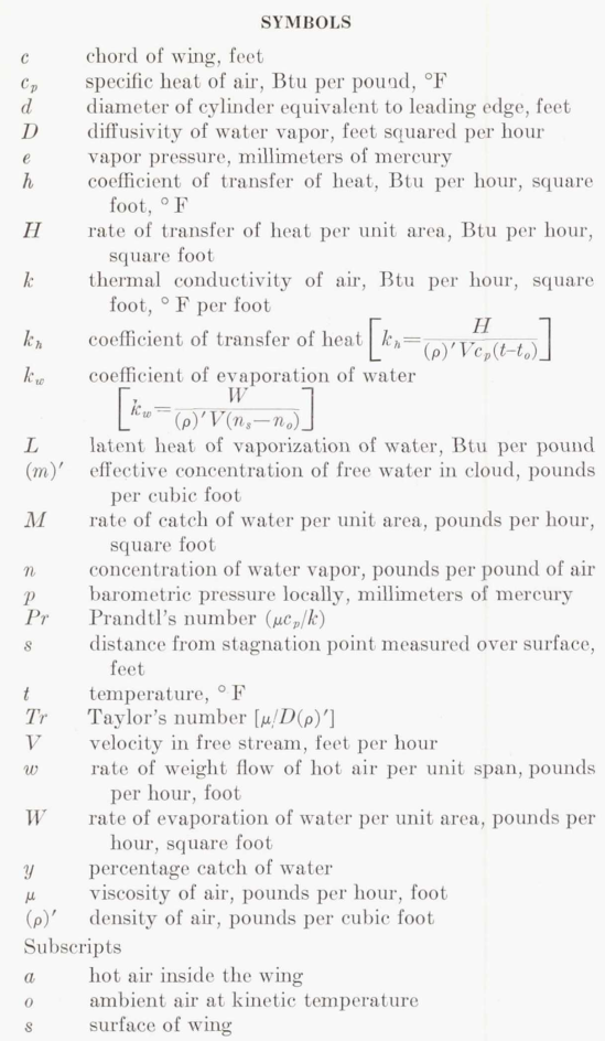
The nomenclature may be challenging, so peruse the symbols used:
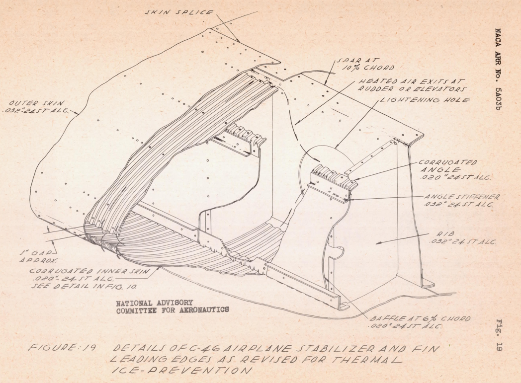
The ice protection heat exchanger is described in detail in NACA-ARR-5A03b.
Hot air from an internal "D" chamber enters a corrugated heat exchanger near the leading edge.
The thermal performance calculations are detailed. Large portions are reproduced herein:
THEORETICAL ANALYSIS
CLEAR AIR
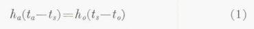
In clear air, the equation which gives the balance of the flow of heat to and from the surface is
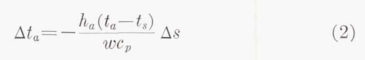
The equation which gives the change in temperature of the hot air t_a, as it flows over the inner surface is
Values of t_s and t_a, which satisfy both equations, are found by trial. These are the mean values for a strip of width Δs in a chordwise direction and unit length spanwise. Equation (2) is inexact, since the air flowing through the space between inner and outer skins receives heat through the back of the corrugations from the air as it flows from the main duct to the entry to the corrugations. A more exact equation is
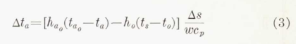
h_a_o is the over-all coefficient of transfer of heat from the hot air behind to the hot air within the corrugations and t_a_o is the temperature of the air before entering the corrugations. In the present analysis, equation (2) has been used throughout. A trial calculation has been made using equation (3); the results of this calculation will be discussed later.
Equations of heat flow. In conditions of icing, droplets of water strike the surface in an area about the stagnation point. The rate of dissipation of heat from the area on which the droplets strike is given by the equation
where cp_w is the specific heat of water. This assumes that the temperature of the water caught is raised from that of the air to that of the surface. The temperature of the air t_o is the kinetic temperature in wet air as derived in reference 4.

"Reference 4" is NACA-ARR-4I11 2, with Hardy as the author. NACA-ARR-4I11 analyzed an instrument that sampled the ambient air, and the sample was heated to ensure that all water drops evaporated. The vapor pressure of the heated air (measured via dew point) could then be used to calculate the liquid water content of the air.
To calculate t_o, NACA-ARR-4I11 used a table from 3, which I have not been able to find (either the original or the "NACA Reprint"). For the python implementation, I used the t_o calculation method from NACA-ARR-5G13 4.
There is a subtlety here for the ice protection application, which assumes that the water drops and vapor are always in equilibrium with the (dry) air temperature. A dry air calculation yields a static temperature rise as the flow approaches the stagnation point on a surface. The equilibrium assumption requires that a significant portion of water drops evaporate as the flow approaches the stagnation point, before reaching the (possibly) heated surface, lowering the amount of liquid water available to impinge on the surface. The significant latent heat of evaporation involved lowers the "kinetic" temperature (total or recovery temperature, in more recent terminology) relative to a dry air calculation.
Later works in the Thermodynamics thread will use a different assumption, that the water drops are not in equilibrium, with the water drop temperature and vapor concentration essentially unaffected as the flow approaches the object.
Other than lowering the liquid water content available to impinge, the equilibrium assumption probably has a minor effect on the ice protection heating calculation.
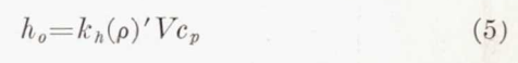
The nondimensional coefficient of transfer of heat k_h is used, since it is related to the coefficient of evaporation k_w. It is related to the more familiar coefficient of transfer h_o by the equation
The evaporation equation form will see some variation in later works.
Equation (4) may be put into a form which is more convenient for computation by substitution from equation (5) and rearrangement.
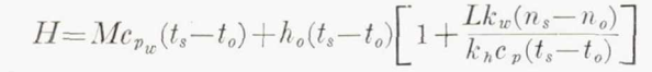
The heat transfer to the external flow may then be linked to the heat transfer from the heated, internal flow:

"X" is a linearization about an operating point of the non-linear evaporation rate.
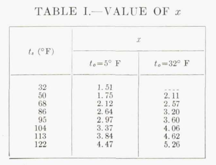
Equation (6) in conjunction with equation (2) is used to calculate the temperature of the surface on which the droplets strike.
Note that this requires an iterative solution, as the surface temperature is not yet known. The "X" value is a non-linear function of surface temperature, "wet kinetic temperature", and pressure. Table I is for the 4000 ft. example altitude.
There follows a discussion about the ratio of k_h to k_w. The values will differ in later works, but:
In the present calculation the ratio of k_w to k_h has been taken as unity.
Rate of water catch
A cylinder is used as an approximation of the wing leading edge to calculate impingement (more on cylinders):
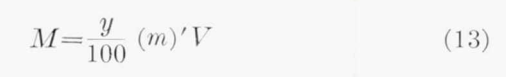
The value of M, the rate at which water from the cloud strikes the leading edge of the wing, is calculated by the method given in reference 9. The wing is considered as equivalent to a cylinder having the same radius as the radius of curvature of the leading edge.
Reference 9 also has Hardy as an author. Hardy, J. K., Hales, K. C., and Mann, G.: Rate of Catch of Supercooled Water on Aerofoils and Cylinders in Flight Under Conditions of Icing. TN No. S. M. E. 207, R. A. E., Jan. 1944.
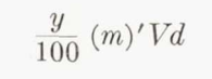
It is necessary to assume a size of droplet in the cloud, since this was not measured in the tests of the C-46 airplane. With an assumed size of drop, the percentage catch y is found from figure 1 of reference 9. The total rate of catch per foot span is
The value of (m)', the effective concentration of water in pounds per cubic foot, is found by deducting the amount of water evaporated by kinetic heating from the concentration specified for the particular conditions of icing. The method of calculating this is shown by the example given in reference 4.
Again, we see the equilibrium assumption that results in a reduced water catch.
An assumed impingement rate curve is constructed:
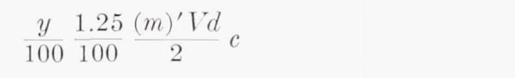
The convention adopted with regard to the distribution of the catch of water on the surface of the wing is to assume that the water is caught in the area between s/c= +/-1.25 percent, and that it is equally distributed over this area except at the stagnation point. At the stagnation point, the rate of catch, it is assumed, is given by the equation
Between s/c =0 and s/c =1.25 percent on either the upper or the lower surface of the wing, the rate of catch for unit span is given by
This method differences from later investigations.
It is noted that the equilibrium assumption may not be applicable in all cases:
There is an important qualification which must be made to the method of calculating the rate of catch of water. In calculating the effective concentration of free water, it is assumed that the droplets respond fully to the change in temperature produced by kinetic heating as they approach the surface. This is consistent with the limited observations which have been made on the C-46 airplane. If, however, the droplets are large and the speed of flight is high, the droplets may not respond fully to the effect of kinetic heating. In consequence, the effective concentration of free water will be greater than that calculated. The response will depend on the size of wing as well as on the size of droplet. The extent to which the severity of icing may be reduced by the effect of kinetic heating at high speeds is not known.
Blown-off water
Blow-off of water. It is evident from equation (8) that no account has been taken of the heat carried by water from the area of catch to the surface behind this area. The reason for the omission is that the water runs back in large drops which cover only a very small area of the surface, and which are blown off the surface early in their travel.
As far as can be judged by eye, the water which strikes the surface collects near the stagnation point until a condition of instability is reached, when a portion of it is blown back as a large drop. This tends to lift from the surface, since its path is curved. It is restrained from lifting by the surface tension of the water, and is subject to deformation by the force of the air. It is probable, under the influence of these forces, that a second state of instability is reached; this results in the disruption of the drop and its dispersal into the air, except for a small residue of water. This residue which continues to flow back over the surface as a small drop, must be dispersed by evaporation before its temperature falls to 32' F, if the formation of ice is to be avoided.
Later works will have different opinions about how much water, if any, is blown off of the surface
Wet surface
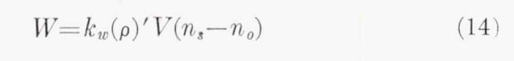
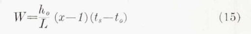
Rate of evaporation.—The calculation of the rate of evaporation of water from the surface, when the surface is completely wetted, presents no difficulty. The rate of evaporation is given either by the equation
or by the equation
When the surface is just wet, the condition reached at the termination of stage 2, the value of M in equation (6) is equal to that of W. In this state, the value of t_s, which must be such as to satisfy this identity, can be found by trial. Behind the point at which water is blown off the surface, there is a formidable difficulty. If it is assumed, as stated in the preceding section, that the residue of water is dis- persed by evaporation, then the surface must be partially wetted only. This requires that equation (8) must be modified to suit this condition. This is not possible without knowing the degree of wetness of the surface. Alternatively, if it is assumed that sufficient water is carried to the surface through the boundary layer to satisfy the requirement of full evaporation, thereby malting equation (8) valid, then the residue of water will not evaporate. The absence of ice from runback, in many of the tests of the C-46 airplane in conditions of icing, suggests that evaporation must occur. It is evident that a detailed investigation is necessary before all can be made of the important process by which analysis of water leaves the surface of the wing. In the analysis of this report it is assumed that the surface is fully wetted.
The assumption about what fraction of the surface is wet where there is runback water will be revisited in later works.
External Heat Transfer Coefficients
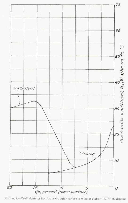
There is a discussion about how the external heat transfer coefficients were determined. There had been previous analysis (5, 6, 7, 8) (and 8 includes the cylinder leading edge approximation). There is much to see here, but this is the thermodynamics thread, so I will stay focused. The method from 5 was used, as it provided laminar and turbulent values.
The values of h_o, used in the analysis, are plotted in figure 1. The form of the transition from the laminar to the turbulent regime which is shown in this figure is entirely arbitrary. It is known that transition, when it occurs in a forward position on a wing, will not be abrupt. The precise shape of the curve of transition is indeterminate.
Later works will use a variety of methods, some similar to the methods described above, to determine external heat transfer coefficients.
Internal Heat Transfer Coefficients
The internal heat transfer coefficient was determined from the external heat transfer coefficient values, the calculated t_o value, and surface and heated air thermocouple readings. So, the accuracy of the internal heat transfer coefficient is dependent on those other values.
The value, used in the analysis, for the coefficient of transfer of heat h d to the inner surface of the wing has been deduced from the actual temperature of the surface, in clear air, measured in flight. Trial calculations were made, using equations (1) and (2) with the values of h_o from figure 1, to find the value of h_o which gave values of t, in agreement with those measured. It was found that a value of 21 Btu per hour, square foot, °F for h_a , constant for the whole extent of the double skin, appeared to be the most satisfactory. This value has been used for all other calculations.
It is difficult to believe that the value of h_a, in the case of the C-46 wing, really is constant. The agreement, therefore, between the terminal value, 19.5 Btu per hour, square foot, °F, calculated from the data of reference 5, and the value used in the calculations must be regarded as fortuitous.
Efforts will continue in later works to determine internal heat transfer coefficients.
Water catch
Results
While the flight conditions where surface temperatures were measured were described as "mild icing", an LWC value of 1.2 g/m^3 was selected [which seems high to me for "mild icing"].
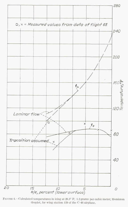
The concentration of free water, for both temperatures, has been taken as 1.2 grams per cubic meter, and the size of droplet in the cloud as 10 microns diameter.
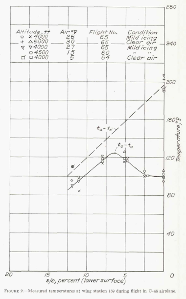
Nonetheless, the calculated surface temperatures in Figure 4 are within about 10F of the measured values. Also, the heated air temperatures match well, indicating that the internal and external heat transfer coefficients used yield a match on overall energy balance (it is possible for more than one set of internal and external heat transfer coefficients to yield similar results).
The calculated effect of different liquid water content values is shown in Figure 6.
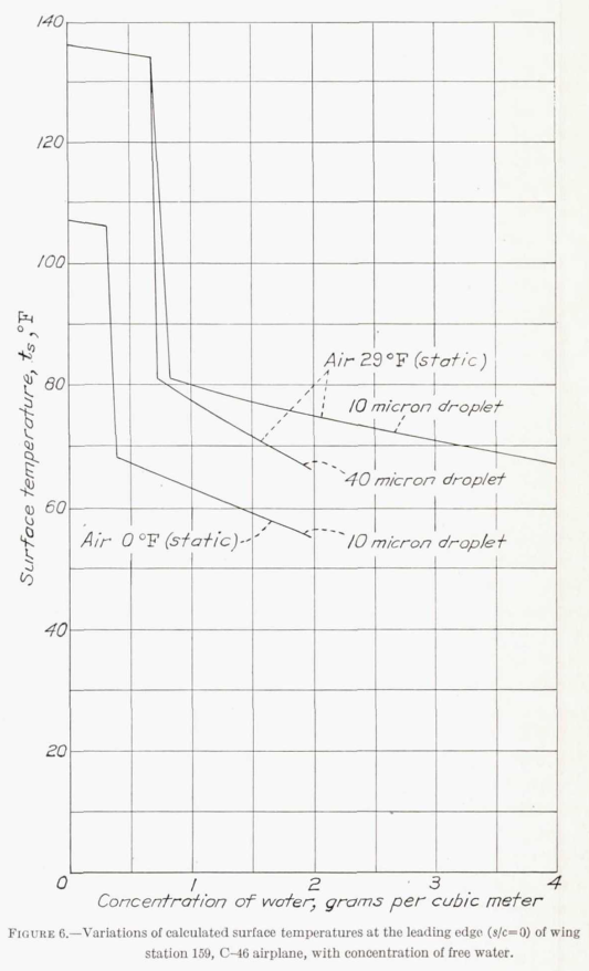
Figure 6 shows some of the effect of the equilibrium assumption. For the 29F, 10 micron case, the predicted surface temperatures are high (similar to the dry air conditions), up to an (ambient) concentration of water of about 0.65 g/m^3. Above that value, the surface temperatures take an abrupt drop to a lower value, as there are water drops, that were not completely evaporated, available to impinge.
Conclusions
It has been shown that the temperature of the surface of the wing in conditions of icing can be predicted with considerable exactitude from the temperatures measured in clear air. It is possible, therefore, to calculate the thermal requirements of a wing which is subject to conditions of icing, if the coefficients of transfer of heat, both to the inner surface and from the outer surface in clear air, are known. For the outer surface, there is little doubt as to the correctness of the method by which the values of the coefficients of transfer are calculated. The uncertainties are the location of the point of transition and the form of the curve of transition from laminar to turbulent flow. There is, as well, the uncertainty as to the effect, on transition, of water on the surface. The rate of transfer of heat from the hot air to the inner surface cannot at present be calculated with any confidence. There is need for systematic experiment to establish the fundamental data required.
The analysis of this report is incomplete, since the point at which water is blown off the wing cannot be predicted, and, behind this point, the heat required to prevent ice is not known. In these circumstances it is not possible to find how far back from the leading edge the double skin should be carried. The optimum distribution of heat also is uncertain. Again, there is need for systematic experiment.
The lack of knowledge as to the physical characteristics of severe conditions of icing, as they occur in nature, is a severe handicap. With this knowledge, the specification for the design of thermal systems of protection can be given in terms of definite conditions of icing.
The confidence that
"the temperature of the surface of the wing in conditions of icing can be predicted with considerable exactitude"
is quickly tempered with a list of uncertainties:
- "The uncertainties of the location of the point of transition"
- "the uncertainty as to the effect, on transition, of water on the surface"
- "The rate of transfer of heat from the hot air to the inner surface cannot at present be calculated with any confidence"
- "point at which water is blown off the wing cannot be predicted"
- "optimum distribution of heat also is uncertain"
- "The lack of knowledge as to the physical characteristics of severe conditions of icing, as they occur in nature, is a severe handicap"
These will be continuing challenges for later works, as well as other items noted above:
- accuracy of the water drop temperature equilibrium assumption
- water rate catch calculations
- details of the evaporation calculation, including the ratio of k_h to k_w
- fraction of water drops blown off of the surface, if any
- fraction wettedness of the surface in the water runback region
NACA-TR-831 included most of the components of more recent, 2D thermal ice protection thermodynamic analysis. And it raised issues to be investigated further. So, I view it as a success.
Citations
NACA-TR-831 cites 14 references:
- Jones, Alun R., and Spies, Ray J., Jr.: An Investigation of a Thermal Ice-Prevention System for a C-46 Cargo Airplane, III - Description of Thermal Ice-Prevention Equipment for Wings, Empennage, and Windshield. NACA-ARR-5A03b, 1945. ntrs.nasa.gov
- Hardy, J. K., and Mann, G.: Prediction of the Rate of Formation of Ice, and the Rate of Heating Necessary to Prevent Ice. TN No. Acre. 1010, R. A. E., Aug. 1942.
- Hales, K. C., and Mann, G.: Investigation of Wing De-icing By Means of Hot Air. TN No. S. M. E. 255, R. A. E., July 1944.
- Hardy, J. K.: Measurement of Free Water in Cloud Under Conditions of Icing. NACA-ARR-4I11, 1944. ntrs.nasa.gov
- Ditton Laboratory Staff: Hot Air De-icing — Heat Transfer in the Double Skin. TN No. S. M. E. 208, R. A. E., Jan. 1944.
- Anon.: Note on Kinetic Heating with Particular Reference to Conditions of Icing. Tech. Note No. 674, R.A.E., June 1942. (NACA Reprint October 1942).
- Goldstein, S.: Modern Developments in Fluid Dynamics. The Clarendon Press, Oxford, 1938.
- Dorsey, N. Ernest: Properties of Ordinary Water-Substance. Reinhold Pub. Corp. (New York), 1940.
- Hardy, J. K., Hales, K. C., and Mann, G.: Rate of Catch of Supercooled Water on Aerofoils and Cylinders in Flight Under Conditions of Icing. TN No. S. M. E. 207, R. A. E., Jan. 1944.
- Squire, H. B.: Heat Transfer Calculation for Aerofoils. NACA-MRR-3E29 (R. A. E., Aero 1783), 1943. abbottaerospace.com
- Jones, Alun R., and Spies, Ray J., Jr.: An Investigation of a Thermal Ice-Prevention System for a C-46 Cargo Airplane, III - Description of Thermal Ice-Prevention Equipment for Wings, Empennage, and Windshield. NACA-ARR-5A03b, 1945. ntrs.nasa.gov
- Allen, H. J., and Look, Bonne C.: A Method for Calculating Heat Transfer in the Laminar Flow Region of Bodies. NACA-TR-764, 1943. ntrs.nasa.gov
- Martinelli, R. C., Guibert, A. G., Morrin, E. H., and Boelter, L. M. K.: An Investigation of Aircraft Heaters, VIII - A Simplified Method for the Calculation of the Unit Thermal Conductance over Wings. NACA-WR-W-14, Mar. 1943. ntrs.nasa.gov
- Selna, James, Neel, Carr B., Jr., and Zeiller, E. Lewis: An Investigation of a Thermal Ice-Prevention System for a C-46 Cargo Airplane, IV - Results of Flight Tests in Dry-Air and Natural-Icing Conditions. NACA-ARR-5A03c, 1945. ntrs.nasa.gov
NACA-TR-831 is cited 8 times in the NACA Icing Publications Database 9:
- Hardy, J. K.: Measurement of Free Water in Cloud Under Conditions of Icing. NACA-ARR-4I11, 1944. ntrs.nasa.gov
- Hardy, J. K.: Kinetic Temperature of Wet Surfaces A Method of Calculating the Amount of Alcohol Required to Prevent Ice, and the Derivation of the Psychrometric Equation. NACA-ARR-5G13, 1945. ntrs.nasa.gov
- Darsow, John F., and Selna, James: A Flight Investigation of the Thermal Performance of an Air-Heated Propeller. NACA-TN-1178, 1947. ntrs.nasa.gov
- Gray, Vernon H., and Campbell, B. G.: A Method for Estimating Heat Requirements for Ice Prevention on Gas-Heated Hollow Propeller Blades. NACA-TN-1494, 1947. ntrs.nasa.gov
- Neel, Carr B., Jr., Bergrun, Norman R., Jukoff, David, and Schlaff, Bernard A.: The Calculation of the Heat Required for Wing Thermal Ice Prevention in Specified Icing Conditions. NACA-TN-1472, 1947. ntrs.nasa.gov
- Gelder, Thomas F., and Lewis, James P.: Comparison of Heat Transfer from Airfoil in Natural and Simulated Icing Conditions. NACA-TN-2480, 1951. ntrs.nasa.gov
- Brun, Rinaldo J., Serafini, John S., and Moshos, George J.: Impingement of Water Droplets on an NACA 651-212 Airfoil at an Angle of Attack of 4°. NACA-RM-E52B12, 1952. ntrs.nasa.gov
- Lewis, William, and Perkins, Porter J.: A Flight Evaluation and Analysis of the Effect of Icing Conditions on the PG-2 Airship. NACA-TN-4220, 1958. ntrs.nasa.gov
An online search found that NACA-TR-831 is cited 13 times in the literature 10.
Notes:
-
Hardy, J. K.: An Analysis of the Dissipation of Heat in Conditions of Icing from a Section of the Wing of the C-46 Airplane. NACA-TR-831, 1945. (Formerly NACA-ARR-4I11a.) ntrs.nasa.gov ↩
-
Jones, Alun R., and Spies, Ray J., Jr.: An Investigation of a Thermal Ice-Prevention System for a C-46 Cargo Airplane, III - Description of Thermal Ice-Prevention Equipment for Wings, Empennage, and Windshield. NACA-ARR-5A03b, 1945. ntrs.nasa.gov ↩
-
Anon.: Note on Kinetic Heating with Particular Reference to Conditions of Icing. Tech. Note No. 674, R.A.E., June 1942. (NACA Reprint October 1942). ↩
-
Hardy, J. K.: Kinetic Temperature of Wet Surfaces A Method of Calculating the Amount of Alcohol Required to Prevent Ice, and the Derivation of the Psychrometric Equation. NACA-ARR-5G13, 1945. ntrs.nasa.gov ↩
-
Squire, H. B.: Heat Transfer Calculation for Aerofoils. NACA-MRR-3E29 (R. A. E., Aero 1783), 1943. abbottaerospace.com ↩↩
-
Neel, Carr B., Jr.: An Investigation of a Thermal Ice-Prevention System for a C-46 Cargo Airplane, I— Analysis of the Thermal Design for Wings, Empennage, and Windshield. NACA-ARR-5A03, 1945. ntrs.nasa.gov ↩
-
Allen, H. J., and Look, Bonne C.: A Method for Calculating Heat Transfer in the Laminar Flow Region of Bodies. NACA-TR-764, 1943. ntrs.nasa.gov ↩
-
Martinelli, R. C., Guibert, A. G., Morrin, E. H., and Boelter, L. M. K.: An Investigation of Aircraft Heaters, VIII - A Simplified Method for the Calculation of the Unit Thermal Conductance over Wings. NACA-WR-W-14, Mar. 1943. ntrs.nasa.gov ↩↩