Public domain image by Donald Cook.
Prerequisites
You need to have completed Anti-Ice Heat Required Calculations.
Introduction
Here, we will see that the values calculated by a multi-node analysis in LEWICE are comparable to the values calculated previously.
Running LEWICE for anti-icing calculations involves (necessarily) more complex inputs. The user has to select which set of external heat transfer assumptions to use. The detailed output files require post-processing to extract the total heat required value.
Discussion
The LEWICE manual describes "deicer" cases that also may be used for
anti-ice heat requirement analysis.
An input is the "IDEICE" value in the case.inp file.
By default, this is 0, and an unheated surface ice analysis is performed.
However, with IDEICE > 0, ice protection analysis is performed,
as detailed in a cased.inp file.
A key input in that file is ievap, which for the cases below is set to
ievap=1, causing a steady-state anti-ice heat required calculation to be performed.
The key sections of the manual discussing the inputs are included below.
6.13. De-icer Input
The program will only ask for the de-icer input file name for cases where IDEICE is not equal to zero.
The IDEICE = 2, IDEICE = 3 and IDEICE = 4 options will perform a detailed thermal analysis within the airfoil, ice, and water. The IDEICE = 2 option is recommended for failed thermal cases with significant ice accretion. The laminar flag, IDEICE = 3, provides consistently better temperature predictions for cases with a clean leading edge. However, it is a less conservative option and has a tendency to overpredict temperatures for some cases. The boundary layer trip flag IDEICE = 4 provides a compromise value between these two options.
The de-icer routines in LEWICE assume the body geometry is a clean airfoil with surface properties as described in Section 10.1. Therefore if the input geometry is an iced airfoil, this option may not run properly. The ICEG2D option may not work for de-icer cases as a result.
The output file “noice.dat” contains output from the simplified 1D thermal analysis. This analysis is provided for all cases where IDEICE > 0. When IDEICE = 1, it is the only thermal analysis performed. It is also performed for IDEICE = 2 to IDEICE = 4 cases as the 1D option does not take significant computation time. Also see Section 10.1.4.4 for additional capabilities when IDEICE = 2 to 4.8.3.11. IDEICE
Default Value: IDEICE = 0
IDEICE is a flag that controls which de-icer model will be invoked. If IDEICE = 0 (default), this routine will not be run. If IDEICE = 1, then a 1D steady state anti-icer will be run to generate an estimate of the heat required to keep the surface ice free. This solution can then be used as a starting point for using the de-icing or anti-icing models. If IDEICE = 2, 3, or 4 the software will access a module to analyze 2D transient icing with heater inputs. For IDEICE = 2, the software will perform the analysis using the standard heat transfer coefficients predicted assuming an ice roughened surface. This option is often preferable for de-icing simulations where ice will form. For IDEICE = 3, the software will use the laminar heat transfer coefficient, which assumes a clean surface. This option is recommended for anti-icing simulations or cases which generate a very small ice shape. For IDEICE = 4, the software will trip the boundary layer at the end of the heated section. This boundary layer trip will work for electrothermal as well as bleed air cases. If heat is applied to the entire surface, this option should produce the same output as the IDEICE = 3 option. IDEICE = 4 option may be useful for cases with significant runback ice.When IDEICE = 2, 3, or 4, the following warning message will be displayed:
This option accesses a module which will run MUCH more slowly than a standard (IDEICE = 0) LEWICE run.
When IDEICE = 3, the following additional warning message will be displayed:
This option will use laminar heat transfer coefficients. Some users believe this option will produce more accurate results for anti-icing cases. However, it is less conservative than the IDEICE = 2 option.
When IDEICE = 4, the following additional warning message will be displayed:
This option will trip the boundary layer at the end of the heated area. Some users believe this option will produce more accurate results for running wet cases. However, it is less conservative than the IDEICE=2 option.
Note: The IDEICE = 2, IDEICE = 3, and IDEICE = 4 options will perform a detailed thermal analysis within the airfoil, ice, and water. The IDEICE = 2 option is recommended for failed thermal cases with significant ice accretion. The laminar flag, IDEICE = 3, provides consistently better temperature predictions for cases with a clean leading edge. However, it is a less conservative option and has a tendency to overpredict temperatures for some cases. The boundary layer trip flag IDEICE = 4 provides a compromise value between these two options.
12.2. noice.dat
This file contains output from the anti-icing calculation. Columns are dimensionless wrap distance from stagnation (s/c), heat required at that control volume (qheat) in kW/m^2 , maximum temperature (T_max) in degrees Kelvin, surface temperature (T_surf) in degrees Kelvin, effective heat transfer coefficient (h_eff) in W/m^2 /K, freezing fraction (f_fract), and evaporative fraction (f_evap). The effective heat transfer coefficient can be used to transfer information from LEWICE to other programs. It is the “effective” value which would need to be input as the convective boundary condition for many commercial or non-commercial CFD programs in order to thermally account for icing effects. Freezing fraction is the fraction which does not evaporate that freezes. For cases where IEVAP = 2, the program takes the amount of heat specified by the user. If this amount of heat is insufficient, ice can form. When IEVAP = 2 and IDEICE = 1, the program will override the standard LEWICE ice accretion and use the result from the anti-icing routine to provide the user with an estimate of runback ice formation neglecting conduction. This result can be compared with the IDEICE = 4 option that includes conduction effects. Evaporative fraction may be slightly less than one for IEVAP = 1 cases since the program iterates on the final temperature.15.13. Case 13: First benchmark conditions with an evaporative hot air anti-icer.
Computation Time: Pentium IV 2.4GHz, 2 s.
Disk Space: 1.8 MB
This example case illustrates the use of the IDEICE = 1 anti-ice capabilities of LEWICE. As the procedure used in LEWICE for IDEICE = 1 anti-icing is less involved than the procedure used for the IDEICE = 2 to IDEICE = 4 options and since this feature has not been validated with experimental data, a warning will appear when this case is run. The user must confirm the warning message to continue the run. Also note that a second warning will be generated because the IDEICE = 1 option is being used. The conditions for this case are the same as Example Case 15, except the de-icer flag has been set to IDEICE = 1. The anti-ice solution provided is a steady-state solution so the choice of time step is irrelevant to that output.
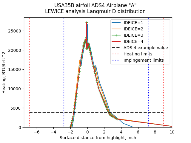
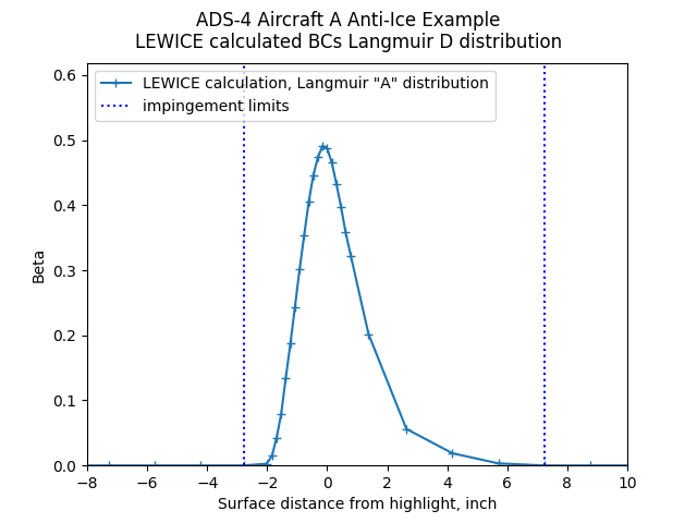
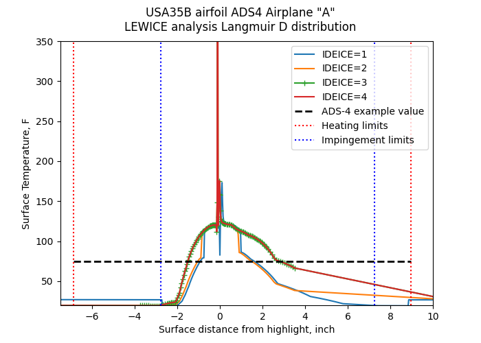
For this analysis, a Langmuir D drop size distribution was used. Here, the impingement limits are interpreted at the nearst points with zero impingement, rather than the widest points with non-zero impingement. This results in slightly different impingement limits than the 40 micrometer impingement limits used in ADS-4.
Public domain image by Donald Cook.
The results with the IDEICE values 1 through 4 are shown below, compared to the results of the ADS-4 analysis.
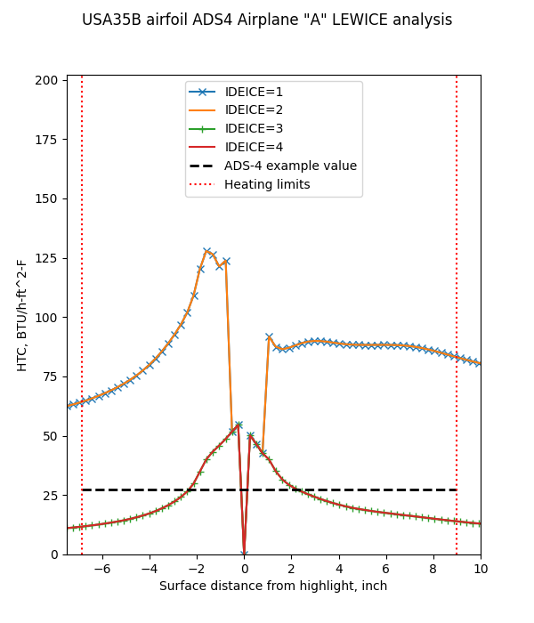
The ADS-4 average heat transfer coefficient value, 27.5 BTU/h-ft^2-F, is comparable to an average value of the cases that assume laminar flw over the heated surface (IDEICE 3 and 4). The other cases (IDEICE 1 and 2) transition to turbulent while still on the heated surface, and have higher heat transfer coefficients.
The LEWICE cases all have a heat transfer coefficient value of zero at the stagnation point. This is a feature of some integral boundary layer method formulations (the method used in LEWICE).
Public domain image by Donald Cook.
The heating values are similar for the four LEWICE analyses. The heating limits do not correspond to the impingement limits.
The ADS-4 value may appear to be lower than the LEWICE values, but the ADS-4 value assumed that the entire heated area was uniformly heated.
LEWICE also calculates small areas of slightly negative values of heating requirements. Those were not included in the plot above, and are not included in the summed values below.
Public domain image by Donald Cook.
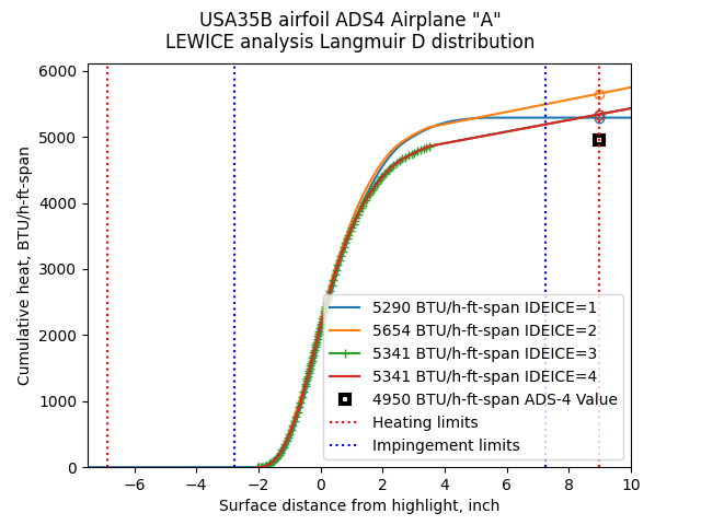
The area under a heat required curve is the total heat required for complete evaporation. The area are summed up as a function of surface distance. For the lower surface (S<0), the values are quite similar, but for the upper surface the values diverge. As some values are still increasing with distance, the upper heated boundary was selected as the point for determining the total heat required. A slightly lower value would result if the impingement limit were used.
The LEWICE method for determining surface point spacings is not well documented. It tends to use a small spacing near the leading edge, and a large spacing further aft. The larger spacing tends to occur prior to the impingement limit, as seen in the case above. The IDEICE=3 case has symbols at the individual points, and there is no surface point between S=3.8 inch to something greater than 10 inch. This is not convenient for determining the values such as the total heat required, and interpretation and interpolation are required as described above.
The LEWICE values are comparable to the ADS-4 value. The ADS-4 values for the Langmuir A distribution agrees well with the LEWICE analysis for the Langmuir A distribution. The LEWICE values vary by about 8% when compared to each other.
Public domain image by Donald Cook.
For surface temperature, the LEWICE values are comparable to one another in the area of laminar flow (about -1 inch to +1 inch). They all have a temperature "spike" near the stagnation point where the heat transfer coefficient value was zero.
The ADS-4 value may appear to be lower than the LEWICE values, but the ADS-4 value assumed that the entire heated area was uniformly heated. Also, comparing surface temperatures for anti-ice cases is challenging, as there are several non-linear effects.
Public domain image by Donald Cook.
Conclusions
For evaporative anti-ice heat required calculations, LEWICE yields similar, but not identical, values to the methods that we have seen before.
As noted in the LEWICE manual, this capability has not been fully validated, particularly for IDEICE = 2, 3, or 4. However, that can be said of the other methods.
Few published studies have attempted to validate the minimum heat supplied for complete anti-icing, let alone the heat required value from any analysis method. Nonetheless, they have been successfully used in design for decades.
LEWICE has an option to calculate performance with heat supplied (ievap=2). However, it is less validated than the anti-ice heat required calculation (ievap=1), and is more complex to use and interpret. As such, those cases are deferred to the yet to be written Advanced Level.
Resources
User's Manual for LEWICE Version 3.2, NASA/CR-2008-214255 ntrs.nasa.gov
Note that a "manual.pdf" file comes with the LEWICE software distribution (apparently for version 3.0),
and a file "Lew32manual_changes.doc".
I find it easier to just use the Version 3.2 manual.
Related
Back to Intermediate Topics