"Icing of air-intake ducts and scoops with subsequent reduction in pressure recovery and in air flow may adversely affect the operation of the aircraft."
From NACA-TN-2999. 1
NACA-TN-2999, "Impingement of Droplets in 90° Elbows with Potential Flow" 1
and
NACA-TN-3770, "Impingement of Droplets in 60° Elbows with Potential Flow" 2
Summary
The impingement of water-drops in idealized elbow ducts is calculated with potential flow.
Abstract
NACA-TN-2999
Trajectories were determined for droplets in air flowing through 90° elbows especially designed for two-dimensional potential motion with low pressure losses. The elbows were established by selecting as walls of each elbow two streamlines of the flow field produced by a complex potential function that establishes a two-dimensional flow around a 90° bend. An unlimited number of elbows with slightly different shapes can be established by selecting different pairs of streamlines as walls. The elbows produced by the complex potential function selected are suitable for use in aircraft air-intake ducts.
The droplet impingement data derived from the trajectories are presented along with equations in such a manner that the collection efficiency, the area, the rate, and the distribution of droplet impingement can be determined for any elbow defined by any pair of streamlines within a portion of the flow field established by the complex potential function. Coordinates for some typical streamlines of the flow field and velocity components for several points along these streamlines are presented in tabular form.
Discussion
In the titles here, the use of potential flow to determine water-drop trajectories gets pushed to the limit. In a demonstration of the pragmatism that ran through much of the ice protection development at NACA, investigators produced results on configurations that could be analyzed that were close enough to real aircraft geometries.
Most of the discussion will center around NACA-TN-3770.
NACA-TN-3770
The air flow through conventional elbows (constant cross-sectional area) cannot be established by potential theory, and, furthermore, the flow is usually three-dimensional. Therefore, it is difficult to calculate droplet trajectories for conventional elbows. Elbows may be designed, however, for which the flow field is determined by two-dimensional potential theory (ref. 13). For these elbows the pressure losses are usually less than those for conventional elbows of comparable size and shape. (Experimentally determined pressure losses presented in ref. 14 for the basic elbow of this report are about one-third of those for a conventional elbow of comparable size.)
Elbow Geometry and Flow Field
As in the case of the 90° elbow of reference 12, the air-flow field for the elbow studied in this report was not determined for a given elbow, but was determined by establishing from potential theory a two-dimensional flow field that makes a 60° turn. From this flow field two streamlines were selected as walls of the elbow. Selection of the complex potential function and streamlines as walls was based upon the following criteria:
(1) The air-flow field should be uniform and rectilinear at some point before and after the bend, in order that the elbow may be fitted to straight ducts.
(2) The resultant velocity at any point inside the elbow should not exceed the velocity U where the flow is uniform and rectilinear. This criterion was selected so as to minimize possible flow separation.
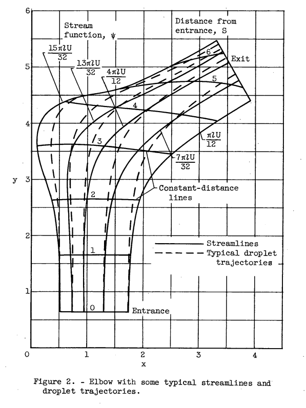
(3) No streamline should have singular points (0 or infinite velocity) within the elbow.For this droplet impingement study the streamline pattern of figure 1 [or 2] is divided into three classes of elbows:
(1) The elbow defined by streamlines ψ = πlU/12 and ψ = 4πlU/12 is defined as the basic elbow.
(2) Elbows defined by any pair of streamlines between those of the basic elbow or by one streamline of the basic elbow and any other intermediate streamline are designated as supplementary elbows.
(3) Elbows whose outside wall is defined by the streamline ψ = 15πlU/32 are designated as pocket elbows.
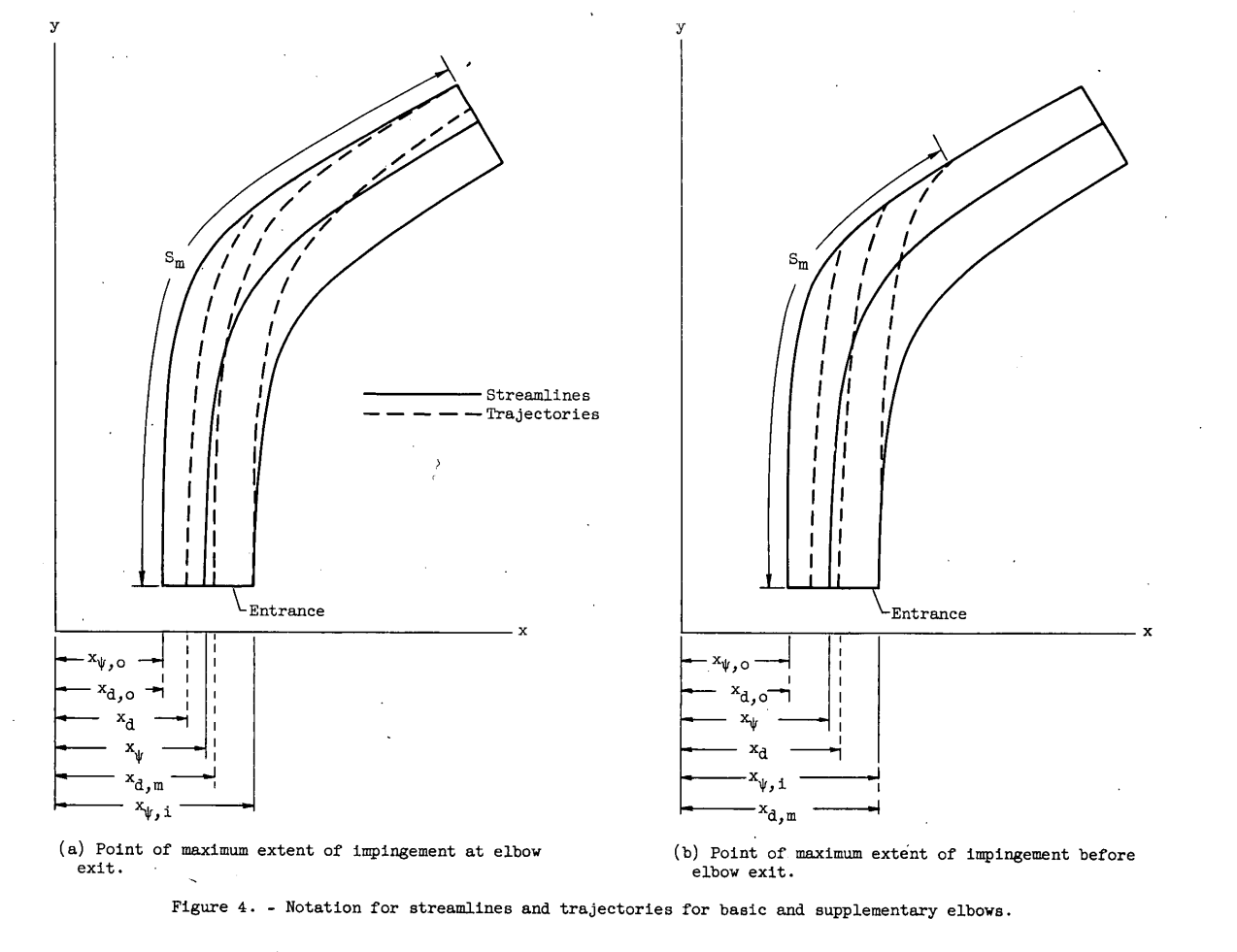
Maximum extent of impingement. - The maximum extent of impingement for the basic elbow S'm for a given combination of K and Reo is determined from figure 5 by the maximum value of S'm for any value of xa within the walls of the elbow. For some combinations of K and Reo such as K = 1 and Reo = 32 (fig. 5(b)), impingement occurs throughout the entire length of the elbow with some droplets passing through without impinging, as is illustrated in figure 4(a). For other combinations of K and Reo, such as K = 4 and Reo = 128 (fig. 5(c)), the impingement of all droplets is confined to a portion of the outside wall, as is illustrated in figure 4(b).
Conclusions
NACA-TN-2999
CONCLUDING REMARKS The special 90° elbows for which droplet impingement data are presented in this report are suitable for use in aircraft air-intake ducts and as droplet inertia separators. For droplet inertia separators, it may be necessary to combine two or more elbows so as to produce a turn of 180° or more in order to obtain satisfactory separation of droplets from the air. The impingement data for supplementary elbows defined by streamlines near the inside wall of the basic elbow can probably be used to approximate droplet impingement in conventional elbows with long radii of curvature, because streamlines in this region are approximately equidistant apart at all points throughout the elbow (see figs. 2 and 4 and table II).
The maximum extent of impingement for these elbows varies directly with the free-stream Reynolds number and inversely with inertia parameter. In contrast to airfoils, the maximum extent of impingement varies inversely with droplet size. For a given value of free-stream Reynolds number, the collection efficiency for the basic elbow increases with increasing values of inertia parameter until all droplets that enter the elbow impinge upon the outside wall. The value of inertia parameter for which the collection efficiency becomes unity increases with increasing values of free-stream Reynolds number. The length of the outside wall of the basic elbow is 6.46 S units (distance from entrance), and the maximum local rate of droplet impingement occurs between S = 3 and S = 5 for all investigated combinations of free-stream Reynolds number and inertia parameter.
The use of elbows and bends designed according to potential theory for aircraft ducts and inlets has two advantages: The pressure losses are much less than those for conventional elbows or any arbitrary bend; and droplet trajectories with respect to the elbow are obtainable, since the air-flow field is easily established by potential theory. Elbows designed for potential flow need not be restricted to symmetrical 90° bends, for potential functions exist by which elbows with various sizes, odd shapes and angles of bend, and different entrance and exit cross-sectional areas can be designed. ...
The use of elbows and bends designed according to potential theory for aircraft ducts and inlets has two advantages: The pressure losses are much less than those for conventional elbows or any arbitrary bend; and droplet trajectories with respect to the elbow are obtainable, since the air-flow field is easily established by potential theory. Elbows designed for potential flow need not be restricted to symmetrical 90° bends, for potential functions exist by which elbows with various sizes, odd shapes and angles of bend, and different entrance and exit cross-sectional areas can be designed.
NACA-TN-3770
CONCLUDING REMARKS
The 60° elbows for which droplet impingement data are presented in this report are suitable for aircraft air-inlet ducts and would probably have lower pressure losses than bends with constant cross-sectional areas. However, these impingement data are based upon theoretical calculations for an ideal fluid flow and hence there might be some differences between theoretical and experimental impingement for the same elbow. Although the collection efficiency of the 60° pocket elbow with the same entrance width as the basic elbow is less than for the 60° basic elbow and the pocket elbow would not be as useful as a droplet inertia separator, the pocket elbow has some impingement characteristics that may be useful. The droplet impingement for pocket elbows is limited to a much smaller area than for the basic elbow; therefore, less area would have to be heated to prevent or remove ice. There is also a region from the entrance to a surface distance of 3.75 on the outside wall of the pocket elbow where there is no impingement. The impingement data for supplementary elbows defined by streamlines near the inside wall of the basic elbow can probably be used to approximate droplet impingement in conventional elbows with long radii of curvature, because the streamlines in this region are approximately equidistant at all points throughout the elbow.
Some inlet duct applications provide ice protection. Here is an example from reference 3:
Even though water-drops may impinge on only a limited area of the duct for a particular case (combination of altitude, airspeed, drop size, flow rate, etc.), the potential impingement area for a range of cases may be large. This design provides heating for the entire duct, which removes the impingement analysis uncertainty for extent, but perhaps not intensity.
Citations
From scholar.google.com:
NACA-TN-2999 14 citations
NACA-TN-3770 No citations (google could not find any)
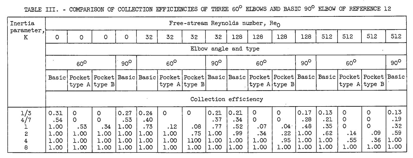
It is a pity that NACA-TN-3770 is not more widely cited. It includes a comparison of 60° and 90° duct bends that may be instructive. I know of more aircraft applications with 60°-ish bends (such as the L-1011 and 727 engine inlet ducts) than for 90° bends.
Related
This is part of the Water Drop Impingement on Surfaces thread.
Notes
-
Hacker, Paul T., Brun, Rinaldo J., and Boyd, Bemrose: Impingement of Droplets in 90° Elbows with Potential Flow. NACA-TN-2999, 1953. ntrs.nasa.gov ↩↩
-
Hacker, Paul T., Saper, Paul G., and Kadow, Charles F.: Impingement of Droplets in 60° Elbows with Potential Flow. NACA-TN-3770, 1956. ntrs.nasa.gov ↩
-
Werner, J. B., Ice Protection Investigation for Advanced Rotary-Wing Aircraft. US Army Air Mobility Research and Development Laboratory, 1973. apps.dtic.mil ↩